Single-layer ETFE roofs are lightweight, transparent, and well suited to long-span architecture, but their drainage behavior is different from that of rigid metal or glass roofs. On a shallow, nearly flat ETFE panel, the main risk is not simply that the nominal slope looks small. The critical problem is a local depression that develops under rain load: water collects, the membrane deflects further, and the deeper depression attracts more water. That feedback loop is the mechanism behind roof ponding.
This guide uses the BIM model, detail drawings, measured dimensions, and on-site rectification records from a 1:1 ETFE mock-up for Qingdao Youth Football Stadium to answer a practical design-and-construction question: how can a project team reduce single-layer ETFE roof ponding risk before large-area installation begins?
Scope and design boundary
Every dimension and construction detail below comes from the Qingdao Youth Football Stadium ETFE mock-up. Other projects must be designed for their own local design rainfall intensity, span, support system, architectural geometry, and formal structural calculations. The case-study values are not universal ETFE specifications.
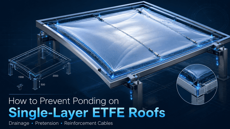
Why does water pond on a single-layer ETFE roof?
Unlike a rigid roof panel, a single-layer ETFE membrane does not have continuous stiff backing. The film has very low self-weight and changes shape under the combined effects of self-weight, water load, and membrane tension. At the same time, stadiums and other long-span buildings often aim for a visually calm, relatively flat roof surface, which can result in a shallow construction slope.
When those two conditions are combined, local slackness or a small geometric low point becomes highly sensitive to rain load. The first water accumulates at the low point, the added weight pulls the film farther down, and the deeper sag attracts still more water. The engineering objective is to stop this ponding-sag-more-ponding cycle from developing.
For that reason, a single-layer ETFE drainage design should not start with only one question—”What roof slope should we use?” It should also answer three practical questions:
- Does the membrane surface have continuous drainage ridges that divide and direct runoff?
- After tensioning, are there any remaining local depressions or slack zones that can become new low points?
- When water reaches the perimeter, can it enter the gutter without being blocked by a seam, fixing, profile, or node?
If these questions are not resolved during design and mock-up testing, discovering the problem only after a water test or rainfall can lead to membrane removal, cable readjustment, node replacement, or rework at the perimeter drainage interface.
How is single-layer ETFE drainage different from PTFE or PVC tensile membranes?
This is one important difference between shallow single-layer ETFE panels and common PTFE/PVC tensile-membrane roofs. PTFE and PVC roofs often use more pronounced double-curved forms and higher pretension, so the drainage route is more visibly built into the geometry. A nearly flat single-layer ETFE panel depends more heavily on the combined control of reinforcement cables, pretension, and edge/node detailing. The drainage strategy and acceptance checks should therefore match the material and structural system rather than being copied directly from another membrane type.
Case study: what did the 1:1 ETFE mock-up at Qingdao Youth Football Stadium test?
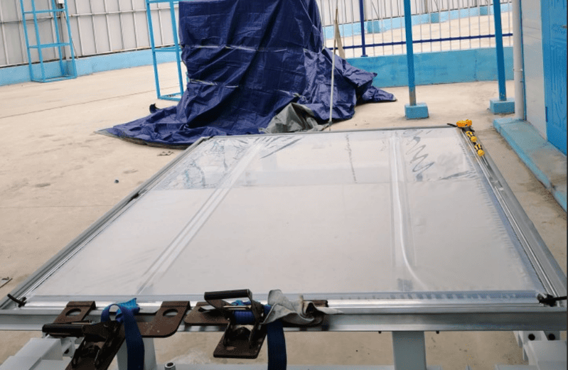
According to the project team records, Qingdao Youth Football Stadium uses a single-layer ETFE membrane-and-cable system. Before large-area installation, the team built a full-scale mock-up to verify the membrane, reinforcement cables, clamping profiles, fixing points, and construction tensioning. The mock-up was not intended only as a visual sample; it was used to make the drainage path and the installation method physically testable.
| Item | Qingdao Mock-up Data | What the Check Was Used For |
|---|---|---|
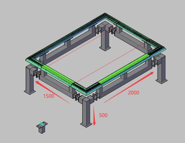
| Mock-up unit size | 1,500 × 2,000 × 500 mm | Full-scale verification of construction details, tensioning and drainage geometry |
| Reinforcement-cable sleeve width | Approx. 75 mm | Project-specific heat-welded sleeve used to transfer load between cable and ETFE film |
| Aluminum center clamping profile | 1,500 × 2,005 mm | Controls membrane-edge collection, drainage and perimeter geometry |
| Clearance from PE fixing point to membrane | ≥ 50 mm | Helps keep a fixing node from touching the film and becoming a local ponding point |
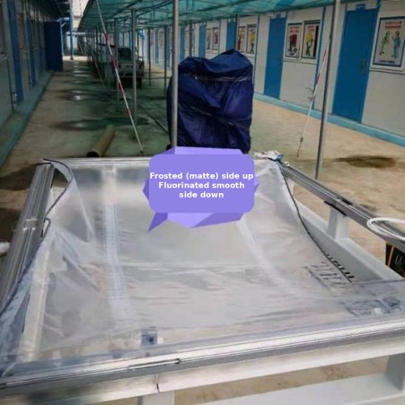
| Film orientation | Frosted/matte side up; fluorine-treated smooth side down | Orientation had to be consistently marked during packing, unfolding and installation |
| Site mock-up records | October–November 2021 | BIM, detail drawings, installation photos and rectification records |
How do reinforcement cables create a reliable drainage path on single-layer ETFE?
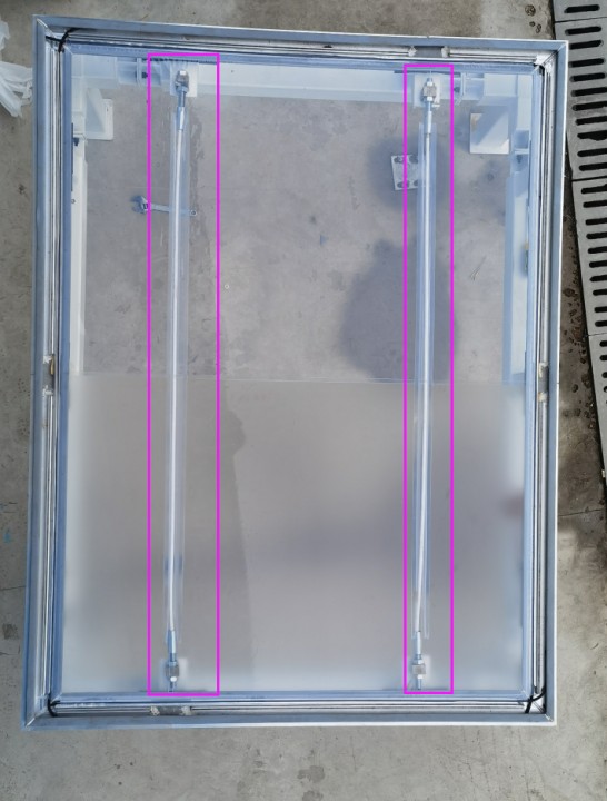
The central drainage strategy in the Qingdao mock-up was to place reinforcement cables inside each ETFE unit along the intended direction of water flow. Once the cables were tensioned, the membrane was no longer treated as a nearly flat sheet. Instead, it was shaped into a continuous, gently undulating surface: the cable lines formed drainage ridges, the spaces between them formed shallow drainage channels, and rainwater was directed toward the perimeter aluminum gutter system.
In other words, the roof should not wait for rainwater to “find its own way.” The drainage route should be created during design and tensioning. For a shallow single-layer ETFE roof, that geometric control is more important than relying on a slope percentage alone.
How should ETFE reinforcement cables be laid out?
Reinforcement-cable spacing cannot be selected independently of drainage area and local design rainfall intensity. In this mock-up, the ridges formed by the reinforcement cables controlled how the membrane divided runoff. The heat-welded cable sleeve was approximately 75 mm wide—a Qingdao project value used to maintain continuous load transfer without concentrating force too sharply at the film.
Pretension is equally important. Simply placing a cable under the film does not create useful drainage. After tensioning, the membrane must hold a stable curved form. One straightforward field check is the membrane condition after rainfall or a controlled water test: there should be no obvious area that remains persistently depressed. If a low point remains, the team should investigate cable length, tensioning sequence, and node restraint rather than attributing the problem only to heavy rain.
How should ETFE seams be detailed so they do not become water traps?
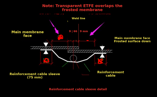
In the Qingdao mock-up, the transparent film was joined over the frosted film. The seam used a heat-welded transparent cover strip with an approximately 9 mm overlap, an approximately 66 mm central cavity, and an approximately 9 mm return. The purpose of this arrangement was to let water near the seam continue along the outer cover surface instead of entering and being retained between two membrane layers.
The useful design lesson is not to copy the “9-66-9” dimensions. Those numbers are case-specific. The general principle is that the seam must be oriented with the direction of runoff, and the uppermost membrane layer must maintain a continuous shingled/covering relationship. Other projects may use different dimensions, but the detail should avoid reverse laps, local depressions, or cavities that can capture water.
How do ETFE film orientation and tensioning affect ponding risk?
Mark the correct ETFE film face at every handling stage
The Qingdao mock-up specified the frosted/matte face upward and the fluorine-treated smooth face downward. The project team controlled film orientation together with daylighting, surface condition, and later drainage acceptance. On-site, the most important management step was consistent marking through packaging, unfolding, laying, heat welding, and tensioning so an installation-direction error would not be discovered after the film had already been clamped and tensioned.
This may appear to be a minor drawing note, but on a single-layer ETFE roof it becomes expensive to correct once the membrane is installed in the clamping profile and fully tensioned. The mock-up and installation briefing are the right stages to standardize the orientation-marking method.
Use symmetric, staged tensioning—not simply “as tight as possible.”
The Qingdao mock-up did not use nominal roof slope as the only acceptance criterion. The perimeter clamping profiles and internal reinforcement cables restrained the film together so that the panel formed a continuous, slightly crowned surface—relatively higher toward the center and lower toward the perimeter—allowing runoff to move naturally toward the edge gutters.
A key site lesson was that asymmetric tensioning can load one area too early, creating wrinkles and slack zones. Those areas can later become low points under water load. The project therefore used symmetric, staged tensioning and tensioners for correction. Acceptance should not stop at confirming that the cables are “tight”; the entire membrane surface should look continuous and even, without isolated depressions.
What if severe wrinkles remain after tensioning?
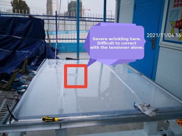
A mock-up record dated November 4, 2021, documented a location with severe bunching/wrinkling that was difficult to correct with a tensioner alone. The project team did not carry the defect into the next construction stage; it went back to cable length and node conditions and adjusted the underlying geometry.
This is important because wrinkles are not only a visual defect. They indicate that the intended force distribution and geometry have not been achieved. When wrinkles appear, check the tensioning sequence, reinforcement cable length, node position, and edge restraint first. Increasing local pulling force without correcting the root cause can simply move the problem from one area to another.
How should ETFE roof nodes and gutters be detailed to avoid local ponding?
Many drainage failures do not originate in the middle of a large membrane panel. They occur in the last few tens of millimeters around a fixing, clamp, or connection. If a component sits directly against the ETFE surface, its base can interrupt runoff and create a small dam. Persistent wetting can also increase durability concerns around aluminum and connection components.
Keep fixing points clear of the membrane: ≥ 50 mm in the Qingdao mock-up
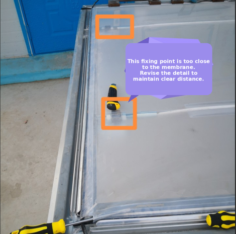
During the mock-up stage, the team found fixing nodes that were too close to the membrane. The response was clear: maintain a physical gap between the node and the film. The Qingdao ETFE sample located four PE fixing points and required more than 50 mm clearance from the membrane surface. Where a fixing point touched or crowded the film, the preferred response was to adjust or replace the node detail rather than depend on future cleaning and maintenance.
Check aluminum clamping profile elevation, straightness and gutter continuity
The Qingdao mock-up used a 1,500 × 2,005 mm aluminum center clamping profile as an important membrane-edge collection and drainage component. Its elevation, straightness, and connection to the gutter directly affect whether the perimeter develops backwater, retained water, or a local low point.
Before fabrication and installation, the project used the BIM model to check field survey data. The goal was to reduce the mismatch between actual dimensions and the model before cumulative errors reached the gutter and edge nodes. For a long-span venue, a “survey – verify model – fabricate” workflow is more reliable than waiting to trim or modify the drainage edge after installation.
Why is a 1:1 ETFE mock-up critical before full roof installation?
Many single-layer ETFE drainage risks are difficult to expose completely in drawings and calculations but become obvious in a full-scale mock-up. The team can see whether the film face is correct, whether the reinforcement cables actually create ridges, whether nodes touch the membrane, whether the clamping profile connects smoothly to the gutter, and whether the film develops wrinkles after tensioning. These conditions can be photographed, measured, and recorded.
The Qingdao project first built a 1,500 × 2,000 mm full-scale unit and trial-assembled the film orientation, cable tensioning, node clearance, and gutter interface. Problems were corrected during the mock-up stage, and the confirmed method was then used as the basis for broader installation. The value of this step is that “reliable drainage” becomes inspectable physical evidence rather than only a design statement.
What should owners, architects, and contractors specify to control ETFE ponding risk?
For an owner, architect, facade consultant, or main contractor, a tender note that says only “the ETFE roof shall not pond” is difficult to inspect. A more effective approach is to specify the process checks that make drainage performance verifiable. Based on the Qingdao mock-up, the following items should be made explicit before large-area work proceeds:
| What to Specify | What Should Be Verifiable on the Project |
|---|---|
| Drainage geometry | Identify the drainage ridge(s), channel(s), edge collection point(s), and final gutter for each ETFE unit so the runoff path is continuous. |
| Reinforcement cables and pretension | Define cable-layout principles, tensioning sequence, and adjustment method, including what to do if wrinkles, slackness, or local depressions remain. |
| Node clearance | Inspect every fixing, connector, and clamp that could approach the membrane and confirm that it does not create a water dam or ponding point. |
| BIM and field verification | Check field-survey dimensions before clamping profiles, nodes, and gutters are fabricated so cumulative errors do not concentrate at the drainage edge. |
| 1:1 mock-up approval | Use the mock-up to establish accepted workmanship for film orientation, heat-welded seams, cable tensioning, nodes, profiles, and gutters before mass installation. |
| Post-rain / water-test observation | Acceptance should check not only leakage but also persistent membrane sagging, low-point ponding, retained water at nodes, and discontinuous gutter drainage. |
For management decision-makers, the mock-up is not just a display sample. It uses a small, controlled test area to reduce uncertainty before the roof is repeated across dozens or hundreds of units. The expensive scenario is not the mock-up itself; it is removing installed film, re-tensioning cables, changing nodes, or rebuilding gutters after large-area installation is already complete.
What should be checked during single-layer ETFE roof maintenance?
Drainage performance still needs periodic inspection after handover. Based on the project experience documented in the source material, the following three areas deserve particular attention before and after the rainy season:
| Inspection Area | What to Look For |
|---|---|
| Reinforcement cables | Check for obvious slackening, changes in effective cable length, or local imbalance in tension. |
| Membrane surface | Look for new wrinkles, persistent depressions, traces of local ponding, or abnormal deformation. |
| Edge gutters and nodes | Remove debris and check for retained water marks, water-blocking points, or blocked outlets or nodes that remain wet for long periods. |
If a problem is found, use the workmanship standard established during the mock-up to trace the cause and correct it rather than relying only on surface cleaning. Mock-up records, node photographs, and tensioning data remain useful during operations and maintenance.
Conclusion
The practical lesson from the Qingdao Youth Football Stadium mock-up is clear: preventing ponding on a shallow single-layer ETFE roof starts by shaping the membrane into a continuous drainage geometry with reinforcement cables and pretension. The water then has to move through correctly oriented seams and past clear fixing nodes into accurately aligned edge profiles and gutters without interruption.
Any one of those elements can create a new low point if it is not controlled. The most effective risk-reduction step is therefore to build the complete detail at a 1:1 scale before mass installation, observe it, correct it, and turn the final method into an enforceable standard for tendering, construction, and acceptance.
If a project is still at concept design, it is usually more useful to define the local design rainfall intensity, unit span, support system, architectural geometry, and gutter conditions first than to search for a universal “ETFE roof slope.” Those inputs should determine reinforcement cable layout, drainage direction, and tensioning control for the specific roof.
Project data and technical limitations
- Project: Qingdao Youth Football Stadium (Asian Cup) ETFE sample/mock-up work; field records and BIM model dated October–November 2021.
- According to the project team records, the project uses a single-layer ETFE membrane-and-cable system. According to project-team follow-up reported through 2026, no roof leakage or ponding had been reported since the roof entered service in 2022.
- Mock-up values: 1,500 × 2,000 × 500 mm; reinforcement-cable sleeve approximately 75 mm; aluminum center clamping profile 1,500 × 2,005 mm; clearance from PE fixing point to membrane ≥ 50 mm; frosted/matte side up and fluorine-treated smooth side down.
- Image sources: project site photographs, BIM model, ETFE seam detail, and node detail. All dimensions in this article are project case data. Other projects must follow their formal structural calculations, approved design drawings, and local design conditions.
FAQ
There is no single slope percentage that answers this safely. The project team’s experience referenced in the source includes near-flat single-layer ETFE conditions below 3% nominal construction slope, but 3% is not a universal design limit. Ponding performance depends on the final curved geometry, drainage ridges formed by reinforcement cables, pre-tension, and control of local low points. The actual slope must be determined together with span, design rainfall intensity, structural calculations, and architectural form.
In the Qingdao mock-up, the reinforcement cables were on the inside of the membrane, and the cable sleeve was approximately 75 mm wide. From below, this mainly reads as a continuous longitudinal linear feature. Whether that visual effect is acceptable should be decided during architectural design. From a drainage and form-control perspective, however, the cables have a defined structural and drainage function and should not be judged only by whether they are visible.
Yes. Wrinkles generally indicate uneven tensioning or local slackness, and a slack area can become the starting point for further deflection under water load. When wrinkles are found, first check the tensioning sequence, reinforcement cable length, and node restraint. The Qingdao mock-up recorded severe bunching that could not be solved by a tensioner alone and required adjustment of the underlying conditions.
Not without project-specific engineering review. PTFE/PVC tensile membranes commonly use more obvious curvature and higher pretension, which makes the drainage path more geometrically pronounced. A shallow single-layer ETFE roof is lighter and more deformable and therefore depends more strongly on reinforcement cables, tensioned form, edge profiles, and node coordination. The design and acceptance priorities should reflect the actual membrane system.
Because the mock-up converts an abstract drainage concept into something that can be seen and measured. It shows whether reinforcement cables actually form ridges, whether the membrane contains low points, whether nodes block runoff, whether the gutter connection is continuous, and whether workers can install and tension the film in the intended sequence. Finding one unit-level problem early is much easier than correcting the same issue after dozens or hundreds of roof units have been completed.

She has over 20 years of experience in tensile membrane structure design, engineering, and manufacturing, with extensive expertise in delivering custom solutions for commercial and architectural projects.