If you are evaluating a tensile membrane roof, stadium canopy, entrance structure, or large-scale shade system, one of the first questions to answer is not simply whether a particular membrane material is “good.” A more useful question is, “What components make up a complete tensile membrane structure, and how do they work together to transfer loads safely into the supporting structure and foundations?”
From an engineering and procurement perspective, a typical tensile membrane structure can be divided into five main systems: the membrane system, supporting structure, cable and tensioning system, connection nodes and hardware, and anchorage and foundations. Drainage, waterproofing, corrosion protection, and maintenance provisions are not always classified as primary structural components, but they still have a major influence on long-term performance.
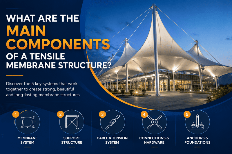
The 5 Main Components of a Tensile Membrane Structure
| Main Component | Primary Function | Typical Materials or Parts | What Should You Check? |
|---|---|---|---|
| 1. Membrane System | Forms the architectural surface and carries in-plane tensile forces under prestress | PVC/PVDF, PTFE, ETFE | Material properties, seams, patterning, compensation, edge reinforcement |
| 2. Supporting Structure | Creates high points, low points, and stable boundaries while resisting membrane and cable reactions | Steel columns, masts, arches, trusses, space frames | Stiffness, stability, node coordinates, fabrication accuracy, corrosion protection |
| 3. Cable and Tensioning System | Controls membrane boundaries and curvature and transfers tensile forces toward supports | Edge cables, ridge cables, valley cables, stabilizing cables, tensioners | Cable force, length, end fittings, adjustment range |
| 4. Connection Nodes and Hardware | Connects the membrane, cables, and steel structure and transfers concentrated forces | Membrane plates, corner plates, cable terminals, clevises, pins, bolts | Load direction, installation angle, tolerances, adjustability |
| 5. Anchorage and Foundations | Transfers structural reactions into the main building structure or the ground | Base plates, anchor bolts, embedded plates, cable anchors, concrete foundations | Uplift, horizontal forces, overturning, existing-structure capacity |
A simple way to remember the load path is: external loads → membrane → cables and connection nodes → supporting structure → anchorage and foundations.
Once this load path is clear, it becomes much easier to understand why a tensile membrane structure is not simply “fabric stretched over a steel frame.”
1. Membrane System
The membrane is the most visible part of a tensile membrane structure, but it is not simply a waterproof covering. After installation, the membrane must maintain the required prestress and develop a stable three-dimensional form. When the structure is exposed to wind, rain, snow, and other external loads, the membrane primarily carries these actions through in-plane tensile forces, transferring them toward its edges, cables, and connection points.
Common membrane materials include PVC/PVDF-coated polyester fabric, PTFE-coated fiberglass fabric, and ETFE film. Each material has different mechanical properties, translucency, weather resistance, fire performance, surface characteristics, and fabrication requirements. For this reason, membrane selection should always be based on the specific structure, environment, architectural requirements, and expected service conditions.
The right question is not “Which membrane material is the best?” but “Which membrane material is the most appropriate for this project?”
What Should You Check in the Membrane System?
- Membrane type and specification: The quotation should identify the actual material system and specification rather than using vague descriptions such as “imported membrane” or “high-strength fabric.”
- Seams, edge reinforcement, and corners: These areas form important interfaces where membrane forces are transferred into other components.
- Patterning and compensation: Tensile membrane panels should be developed from the form-found geometry and adjusted for the material’s mechanical behavior rather than cut directly from flat-plan dimensions.
- Fabrication quality control: Incoming material inspection, cutting, welding or heat-seaming, dimensional checks, and finished-product inspection should be clearly defined.
These are not minor factory details. In Yexing’s membrane fabrication process, incoming material inspection and fabric optical inspection are included in production quality control. For the client, this matters because the membrane is not only the architectural envelope; it is also part of the structural load-resisting system.
2. Supporting Structure
Membrane materials do not have the bending stiffness of conventional steel beams, so they require a stable supporting system to establish high points, low points, edges, and other structural boundaries. Common supporting components include steel columns, masts, arches, beams, trusses, and space-frame structures. In some retrofit or rooftop projects, the membrane system may also connect directly to an existing building structure.
The supporting steel does much more than simply hold up the membrane. It may need to resist membrane prestress, cable tension, wind-induced forces, snow loads, and concentrated reactions transferred through connection nodes. Member stiffness, column-top coordinates, connection locations, and foundation reactions must therefore be coordinated with the membrane and cable system.
For example, if a membrane corner is defined at a specific three-dimensional coordinate in the design model but the supporting steel is installed significantly away from that position, the difference can affect cable lengths, membrane edge geometry, connection angles, and final tensioning. This is why the quality of a tensile membrane support structure cannot be judged simply by asking whether the steel members “look thick enough.”
What Should You Check in the Supporting Structure?
- Are steel member sizes based on the actual project span, loads, and boundary conditions rather than copied from a similar-looking structure?
- Does the structural analysis include membrane prestress and cable reactions?
- Do column tops, truss edges, and connection coordinates match the membrane detailing model?
- Are fabrication tolerances suitable for the membrane and cable installation requirements?
- Are weld quality and corrosion protection appropriate for the project environment?
For outdoor structures, weld quality and corrosion protection are both important to long-term performance. Yexing’s steel fabrication and quality-control process includes coating thickness inspection and ultrasonic testing, which address corrosion-protection and weld-quality risks more directly than steel thickness alone.
3. Cable and Tensioning System
Not every tensile membrane structure uses the same cable arrangement. However, in cable-supported membrane structures, large-span roofs, and mast-supported systems, cables are often essential structural components. Typical cable types include edge cables, ridge cables, valley cables, tie cables, and stabilizing cables.
| Cable Type | Typical Function |
|---|---|
| Edge Cable | Stabilizes a flexible membrane edge and transfers membrane forces toward corners or supports |
| Ridge Cable | Creates a higher structural line and helps define the membrane’s three-dimensional curvature |
| Valley Cable | Forms a lower structural line and may also influence drainage geometry |
| Tie or Stabilizing Cable | Stabilizes masts or resists forces in specific directions |
| Tensioning Device | Adjusts cable length and helps introduce the required tension during installation |
Cables are not decorative accessories. They help define the structural geometry, stabilize flexible boundaries, and transfer tensile forces toward supporting or anchoring points.
What Should You Check in the Cable and Tensioning System?
- Does the design identify which cables function as edge, ridge, valley, tie, or stabilizing cables?
- Are cable diameter, theoretical length, end fittings, and tensioning hardware defined before fabrication?
- Do cable terminals, turnbuckles, or other tensioning devices provide sufficient adjustment range?
- Is the installation and tensioning sequence coordinated with the membrane and connection details?
Large stadium projects make the structural role of cables easier to see. In Yexing’s Zaozhuang Stadium PTFE membrane roof project, the PTFE membrane roof and cable-truss system work together as part of the same roof structure. In this type of project, the cable system is not an accessory added to the membrane; it is one of the structural components that allows the roof to span a large area and transfer forces into the primary supporting system.
4. Connection Nodes and Hardware
Connection nodes are often relatively small compared with the membrane surface or supporting steel, but they are among the most important and frequently underestimated components of a tensile membrane structure. Typical connection hardware includes membrane clamping plates, corner plates, cable terminals, clevises, pins, bolts, cable clamps, tensioning hardware, and specialized aluminum profiles.
Why Are Connection Nodes So Important?
Distributed tensile forces in the membrane eventually have to be transferred through these components into cables or steel supports. A connection, therefore, needs to satisfy more than strength requirements. It must also match the actual three-dimensional direction of the load, provide sufficient installation space, accommodate realistic tolerances, allow adjustment where necessary, and remain inspectable and maintainable throughout the structure’s service life.
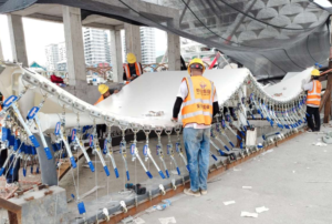
This becomes particularly important in complex membrane geometries. A membrane corner may pull in a direction that is not perpendicular to the supporting steel. If a generic connection is used without considering the actual three-dimensional geometry, cable terminals, membrane plates, and structural steel can interfere with each other during installation.
What Should You Check in the Connection Details?
- How do membrane corners connect to the supporting steel?
- How are edge cables terminated and connected?
- Do cable ends, clevis plates, and steel supports align with the actual force direction?
- Does the connection provide enough adjustment for installation and tensioning?
- Are outdoor connections designed for corrosion protection, drainage, sealing, inspection, and future maintenance?
A connection that is strong enough on paper is not automatically installable on site. For a tensile membrane structure, a successful connection must carry the load, align with the load direction, fit during installation, and provide sufficient adjustment.
5. Anchorage and Foundations
Tensile membrane structures often look lightweight, but that does not necessarily mean their foundations are small. The foundation must resist more than the self-weight of the structure. Depending on the structural form, it may also need to resist membrane prestress, cable tension, mast reactions, wind uplift, horizontal forces, and overturning effects.
Typical anchorage components include base plates, anchor bolts, embedded plates, cable anchors, and concrete foundations. For rooftop additions or membrane structures connected to existing buildings, the anchorage points may connect directly to existing beams, columns, or primary structural members.
What Should You Check in the Anchorage and Foundation System?
| Check Item | Key Question |
|---|---|
| Scope of Supply | Does the quotation include foundations and anchorage, or only the structure above ground level? |
| Support Reactions | Can the structural designer provide the main support and anchor reactions for foundation design? |
| Independent Foundations | Have uplift, overturning, and soil bearing capacity been checked? |
| Existing Buildings | Has the capacity of existing beams, columns, or roof structures been verified? |
| Anchor Bolts and Embedded Parts | Are locations, specifications, and tolerances coordinated with the upper steel structure? |
For rooftop projects in particular, it is unsafe to assume that an existing building can automatically support a new tensile membrane structure simply because the new roof looks lightweight.
What Other Systems Are Needed Beyond the Five Main Components?
If the question is strictly “What are the main components of a tensile membrane structure?” the five systems above cover the primary structural components of a typical project. However, a structure intended for long-term use also requires several supporting systems.
| Supporting System | Typical Elements | Why It Matters |
|---|---|---|
| Drainage | Membrane low points, valleys, gutters, outlets | Helps prevent uncontrolled ponding and directs rainwater away from the membrane |
| Waterproofing and Sealing | Edge closures, penetrations, clamping profiles, joint seals | Affects the actual weather-tightness of the roof or canopy |
| Corrosion Protection | Steel members, cables, bolts, exposed hardware | Influences the durability of outdoor metallic components |
| Inspection and Maintenance Access | Cable terminals, nodes, drainage points, access provisions | Determines how easily critical components can be inspected and maintained |
These systems may not be classified as separate primary structural systems, but overlooking them during design can lead directly to operational and maintenance problems later.
Why Does an ETFE Cushion Structure Have Additional Components?
An ETFE cushion system is not exactly the same as a conventional PTFE or PVC/PVDF tensile fabric structure. A multi-layer ETFE cushion generally requires additional components such as aluminum clamping profiles, sealing elements, air tubes, inflation equipment, and pressure-control systems. For this reason, comparing ETFE solutions based only on the price per square meter of ETFE film can be misleading.
| ETFE Cushion Component | Main Function |
|---|---|
| Multiple ETFE Layers | Form the inflated cushion envelope |
| Aluminum Clamping Profiles | Secure the cushion perimeter |
| Sealing System | Maintain airtightness. |
| Air Tubes | Distribute air to individual cushions |
| Inflation Equipment | Maintains the required internal air pressure |
| Control System | Monitors and regulates cushion pressure |
Yexing’s ETFE membrane guide also uses the Qingdao VR Innovation Center multi-layer ETFE cushion project to illustrate how this type of system works. The project highlights an important point: in an ETFE cushion structure, the film itself is only one part of the complete system.
How Do the Five Main Components Work Together?
The easiest way to understand a tensile membrane structure is to follow the load path rather than memorize individual component names.
Wind, rain, snow, and other external actions → tensile forces develop in the membrane → membrane edges, cables, and connection nodes collect and transfer these forces → columns, masts, arches, or trusses resist the reactions → anchors and foundations transfer the reactions into the building structure or ground.
This means that none of the components should be evaluated in isolation. A higher-grade membrane cannot compensate for an inadequately stiff supporting structure. Larger steel columns cannot correct a poorly aligned corner connection. Higher-strength cables will not solve a problem caused by insufficient tensioning adjustment. Likewise, even a well-designed upper structure will not have a complete load path if the foundations are unable to resist the actual structural reactions.
A tensile membrane structure is therefore not simply a collection of separate components. It is a continuous structural system in which every component affects the performance of the others.
For another large-span reference, see Yexing’s Jinan 60,000-seat stadium roof project, where the membrane roof work illustrates the importance of coordinating multiple structural and construction interfaces within one roof system.
Do All Types of Tensile Membrane Structures Use the Same Components?
The basic structural logic is similar, but the exact configuration varies significantly depending on the structural form. The important point for owners and buyers is that similar component categories do not mean identical component quantities, sizes, or details.
| Structure Type | Typical Component Arrangement | What Should Be Confirmed? |
|---|---|---|
| Frame-Supported Membrane Structure | Rigid steel framing forms most boundaries, with a relatively simple cable system | Frame stiffness, membrane edge connections, corner tensioning |
| Mast- and Cable-Supported Structure | Masts, cables, and membrane work together as a three-dimensional system | Cable forces, anchorage points, mast stability, tensioning sequence |
| Large-Span Cable-Membrane Roof | Cable nets or cable trusses may become part of the primary load-bearing system | Interfaces between cables, membrane, ring beams, and steel supports |
| ETFE Cushion Structure | Adds clamping, sealing, air-distribution, inflation, and control systems | Cushion perimeter details, air-tightness, inflation equipment, maintenance scope |
For this reason, two projects may both be described as “tensile membrane structures” while requiring very different component configurations.
How Can You Tell Whether a Quotation Includes a Complete Tensile Membrane Structure?
When quotations from different suppliers vary significantly, comparing only the total price or price per square meter can be misleading. A better approach is to compare the scope component by component.
| Quotation Category | What Should Be Included? | Common Exclusions |
|---|---|---|
| Membrane System | Material specification, color, seams, edge reinforcement, patterning, and fabrication | Material supplied without detailed design or fabrication |
| Supporting Structure | Columns, beams, trusses, steel connections, fabrication, corrosion protection | Partial supports or finishing are excluded |
| Cable System | Edge, ridge, valley, and tie cables, terminals, tensioners | Generic “cables” listed without detailed scope |
| Connection Hardware | Membrane plates, corner plates, clevises, pins, bolts, special fittings | Custom hardware is charged separately |
| Anchorage and Foundations | Anchor bolts, embedded parts, foundations, or connections to existing structures | The supplier is responsible only for above-ground work |
| Drainage and Sealing | Gutters, outlets, low-point details, edge closures, and seals | Assigned to another contractor |
| Engineering and Detailing | Form-finding, structural analysis, connection details, fabrication drawings, installation drawings | Material supply only |
| Installation and Tensioning | Lifting, tensioning equipment, erection, adjustment, final inspection | Cranes or specialist equipment charged separately |
The purpose of this checklist is to break a single “price per square meter” back down into the actual engineering scope. Only when the component scope, design responsibility, and installation responsibility are comparable does a price comparison become meaningful.
Conclusion
A typical tensile membrane structure consists of five primary component groups: the membrane system, supporting structure, cable and tensioning system, connection nodes and hardware, and anchorage and foundations. Drainage, waterproofing, corrosion protection, and maintenance provisions support the long-term performance of the overall system.
For owners, architects, project managers, and procurement teams, simply remembering these five names is not enough. The more important questions are the following: What does each component do? How does it connect to the next component? Where do the loads ultimately go? Does the supplier’s quotation include all of the necessary components and engineering responsibilities?
When the membrane, steel structure, cables, connections, and foundations form a clear and continuous load path that can also be fabricated and installed as designed, the tensile membrane structure has a much stronger engineering foundation.
If you are planning a stadium roof, commercial entrance canopy, transportation facility, landscape shade structure, rooftop addition, or another tensile membrane project, Yexing recommends preparing the project location, approximate dimensions or span, architectural or CAD drawings, intended use, preferred appearance or transparency, and preliminary schedule before requesting a proposal. The more complete this information is, the easier it becomes to determine which structural components are required, which structural system is appropriate, and what should be included in the project scope.
FAQs
Not necessarily. Steel sections, bolts, some cable fittings, and standard profiles may be commercially available products. However, membrane panel geometry, cable lengths, corner connections, supporting boundaries, and many specialized fittings usually need to be developed for the specific project. This is particularly true for complex architectural membrane forms because every project can have different geometry, spans, boundary conditions, and load directions.
For owners, the more useful question is whether the supplier clearly distinguishes between standard components and project-specific components and whether the customized items are already included in the detailed design.
Not automatically. The membrane can often be treated as a replaceable system, but the existing supporting steel, cables, connections, bolts, and anchorage should be inspected before a new membrane is installed. If these components remain in good condition and are compatible with the new design requirements, some or all of them may be reused. If corrosion, deformation, abnormal cable forces, damaged connections, or new structural requirements are identified, repairs, re-tensioning, or component replacement may be necessary.
That should not be assumed. Different membrane materials can have different weight, stiffness, elongation characteristics, seam requirements, edge details, and prestress behavior. If the membrane material is changed, the designer should confirm whether the existing form, patterning compensation, edge connections, connection details, and structural reactions remain suitable.
Because appearance alone does not reveal the full structural behavior. Two roofs may appear to have a similar cone or saddle shape, but their spans, support positions, wind and snow conditions, membrane segmentation, foundation conditions, and architectural requirements may be very different. These differences can directly affect the number of cables, connection details, supporting steel sizes, and anchor reactions.
In addition to the membrane surface itself, regular inspections should typically pay particular attention to membrane seams and edges, cables and cable terminals, tensioning devices, bolts and pins, exposed steelwork, corrosion protection, drainage low points, and outlets. These areas either transfer structural loads, maintain the required tension, or remain exposed to weather over long periods.
Not necessarily. The number of cables, connections, and supports should be determined by the structural form and engineering analysis. Adding unnecessary components can increase cost while making fabrication, installation, tensioning, and maintenance more complicated. A well-designed tensile membrane structure does not aim to maximize the number of components; it aims to create a clear, continuous, and efficient load path.
Not without verification. An existing membrane may have experienced long-term elongation, relaxation, or deformation during service. The dimensions measured from a removed membrane, therefore, may not represent the original fabrication dimensions. For a replacement project, it is generally more reliable to review the original design information, verify the actual boundary coordinates on site, and consider the mechanical properties of the new membrane material before finalizing new cutting patterns and prestress requirements.

She has over 20 years of experience in tensile membrane structure design, engineering, and manufacturing, with extensive expertise in delivering custom solutions for commercial and architectural projects.