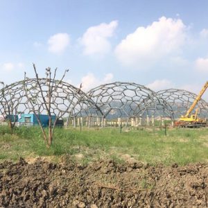
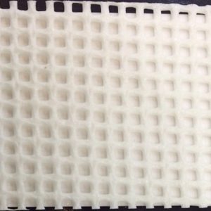
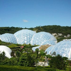
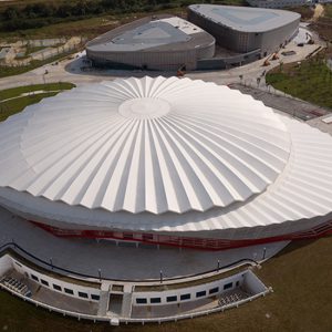
A tensile membrane structure is a lightweight spatial system in which the membrane, cables, supporting steelwork, connections, and initial prestress work together. These structures are widely used for car parks, entrance canopies, stadium stands, commercial plazas, transport facilities, and building atriums.
Unlike a conventional rigid roof, the curved form of a tensile membrane is part of the load-bearing system. Changes to membrane curvature, prestress, support locations, or material properties can affect structural behavior, drainage, connection design, foundation reactions, installation methods, and overall project cost.
For this reason, a buildable tensile structure cannot be developed by focusing only on appearance or comparing membrane prices alone. The membrane, cables, steel supports, connections, foundations, drainage, and site conditions must be evaluated as one coordinated system.
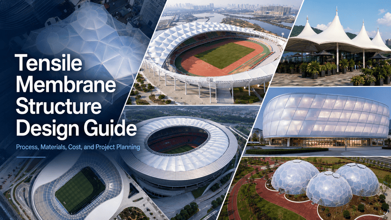
What This Tensile Structure Guide Covers
| Common Project Question | What You Will Learn |
|---|---|
| How is a tensile membrane structure designed? | The complete process, from project requirements and form-finding to fabrication, installation, and inspection. |
| How do PVC, PTFE, and ETFE compare? | How to compare them by service life, light transmission, climate, maintenance, and total system cost. |
| What determines tensile structure cost? | How do span, material choice, steelwork, foundations, design scope, and site conditions affect the budget? |
| What information is needed before a project starts? | The location, dimensions, intended use, site information, budget, and schedule are needed for a reliable proposal. |
Technical note: This guide is intended for early project planning, option comparison, and quotation preparation. It does not replace project-specific engineering. Form-finding, structural analysis, connection design, material specification, and construction documents should be completed in accordance with applicable local codes by qualified professionals with relevant tensile membrane experience.
What Is a Tensile Membrane Structure?
A tensile membrane structure relies mainly on tension within the membrane surface to maintain its form and stability. Because architectural membrane materials are thin and flexible, they cannot hold their shape in the same way as a steel beam or concrete slab. A stable three-dimensional surface must be created through suitable curvature, boundary restraint, and initial prestress.
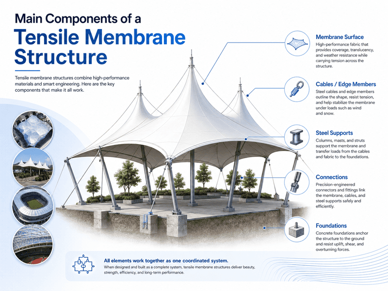
Loads from wind, snow, rain, and temperature effects are transferred from the membrane to the edge, ridge, or valley cables, then to masts, columns, arches, perimeter beams, connections, and foundations. A complete tensile membrane system, therefore, includes much more than the visible fabric.
Typical system components include the architectural membrane, cables, steel supports, tensioning hardware, connection plates, anchorage systems, reinforced-concrete foundations, drainage details, and interfaces with adjacent buildings. Treating the membrane as a simple cover over a steel frame can lead to incomplete load paths, poor drainage, difficult installation, and unreliable cost estimates.
Tensile Membrane Structure Design Process
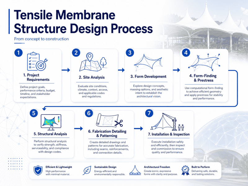
A complete tensile structure design process normally includes seven connected stages:
Project requirements → Site analysis → Membrane form development → Form-finding and prestress design → Structural analysis → Connection detailing and membrane patterning → Fabrication, installation, and inspection
These stages are not independent. Moving one support or changing one high point can affect membrane curvature, cable forces, foundation reactions, drainage, cutting patterns, and cost. Significant changes should therefore be reviewed across the complete structural system rather than treated as isolated drawing revisions.
Tensile Structure Design Process at a Glance
| Design Stage | Main Tasks | Impact on the Project |
|---|---|---|
| Project requirements | Define use, dimensions, service life, budget, and schedule. | Establishes the performance targets and design scope. |
| Site analysis | Review climate, ground conditions, building interfaces, access, and construction constraints. | Influences the support layout, foundations, and installation method. |
| Membrane form development | Set high and low points, curvature, boundaries, supports, and clearances. | Affects appearance, structural behavior, drainage, and usability. |
| Form-finding and prestress design | Develop a stable tensioned surface in equilibrium. | Determines the initial geometry and stability of the membrane. |
| Structural analysis | Check the membrane, cables, steelwork, connections, and foundations. | Verifies strength, deformation, stability, and load transfer. |
| Connection detailing and membrane patterning | Convert the analytical model into fabrication and installation drawings. | Controls manufacturing accuracy and the final tensioned form. |
| Fabrication, installation, and inspection | Manufacture, erect, tension, adjust, and inspect the complete system. | Determines the final construction quality. |
Step 1: Define the Project Requirements and Intended Use
The design team first needs to understand what the structure must achieve. Is it intended primarily for shade, rain protection, daylighting, or full weather enclosure? Will it connect to an existing building? Will people, vehicles, equipment, or emergency routes pass beneath it?
Different functions lead to different design requirements. For example, an open car park canopy used mainly for shade is not designed in the same way as a long-term entrance roof connected to a building façade. The second project normally requires closer attention to waterproof interfaces, drainage falls, edge details, membrane durability, and movement between structures.
| Project Condition | Information to Confirm | Why It Matters |
|---|---|---|
| Intended use | Shade, rain protection, daylighting, or complete space coverage. | Defines the required performance. |
| Coverage area | Length, width, and actual area that must be protected. | Affects membrane quantity and support layout. |
| Structural span | Distance between supporting points. | Influences cable forces, steel sizes, and foundations. |
| Height and clearance | High points, low points, and minimum clear height. | Affects form, drainage, usability, and installation. |
| Expected service life | Temporary, medium-term, or permanent use. | Influences membrane grade and corrosion protection. |
| Light transmission | Opaque, translucent, or highly transparent. | Guides the choice of membrane system. |
| Fire performance | Building use and applicable local requirements. | Affects material specification and approval. |
| Budget | Total project budget, not membrane supply only. | Influences span material, support strategy, and complexity. |
| Schedule | Design, approval, production, foundation, and installation dates. | Determines the delivery plan. |
At the first discussion, four items are especially important: project location, required coverage, intended use, and possible support locations. Late changes to the coverage area, support points, levels, or building interfaces can require new form-finding, structural checks, connection revisions, and membrane pattern updates. Confirming the main dimensions and constraints during concept design helps reduce rework and improves budget reliability.
Step 2: Analyze the Site and Environmental Conditions
Tensile membrane structures are highly sensitive to site conditions. Two projects with the same covered area may require very different solutions because of their location, support options, ground conditions, surrounding buildings, or available installation space.
| Site Information | How It Affects the Project |
|---|---|
| Project location | Identifies applicable codes, climate loads, logistics, and local approval requirements. |
| Site dimensions | Defines the actual coverage boundaries. |
| Adjacent buildings | Influences building interfaces, movement joints, and local wind conditions. |
| Available support positions | Determines possible locations for columns, masts, arches, and anchors. |
| Ground conditions | Affects foundation type, size, and construction method. |
| Underground services | May restrict foundation and anchorage locations. |
| Wind, snow, and rainfall | Influence strength, curvature, deformation, and drainage design. |
| Drainage outlets | Determine low points, gutters, and downpipe locations. |
| Transport and crane access | Affect component sizes, erection sequence, and equipment selection. |
| Membrane laydown area | Influences how the membrane can be unpacked, protected, and tensioned. |
| Traffic or operating restrictions | Affect working hours, phasing, safety measures, and installation costs. |
Site analysis is not limited to measuring length and width. The team must also confirm that loads can travel safely from the membrane through cables, steel supports, connections, anchors, and foundations into the ground.
Before detailed design begins, three practical questions should have clear answers:
- Can the proposed support and anchor points actually be constructed?
- Where will rainwater discharge?
- Can cranes, access platforms, and delivery vehicles reach the installation area?
If these questions remain unresolved, a computer model may be technically complete, but the scheme may still be impossible or unnecessarily expensive to build.
Step 3: Develop the Membrane Form and Support System
The architectural form of a tensile membrane structure cannot be separated from structural behavior. A rendering can communicate visual intent, but it cannot be used directly as a structural model, membrane cutting pattern, or fabrication drawing.
At this stage, the design team coordinates the membrane boundary, high and low points, anticlastic or other suitable curvature, support positions, cable paths, rigid or flexible edges, connections to existing buildings, drainage direction, minimum clearances, and future access for inspection and maintenance.
Common forms include conical membranes, saddle-shaped surfaces, hyperbolic forms, and combined geometries supported by masts, cables, arches, or perimeter beams. The selected form must do more than look attractive: it must develop a stable stress state, drain under service conditions, use buildable connections, and suit the available installation method.
| Design Check | Required Outcome |
|---|---|
| Structural stability | The membrane remains stable under initial prestress and design load cases. |
| Drainage | Water flows continuously toward defined low points and outlets. |
| Clearance | The structure does not obstruct people, vehicles, doors, equipment, or maintenance access. |
| Buildable connections | Supports, anchors, edges, and building interfaces can be fabricated and installed. |
| Maintainability | Inspection, cleaning, adjustment, and repair remain practical. |
| Cost control | Unnecessary long spans, excessively high and low points, and non-standard details are avoided. |
A surface that is too flat may be difficult to stabilize and drain. At the other extreme, adding many high and low points can increase the number of cables, connections, membrane panels, welds, and site adjustments. A more complex shape is not automatically a better design.
Step 4: Carry Out Form-Finding and Prestress Design
Form-finding is the process of calculating the three-dimensional shape in which a membrane reaches equilibrium under defined support boundaries and initial prestress. It is one of the central tasks in tensile membrane design.
A tensile membrane cannot be assigned an arbitrary free-form shape and then forced into position. Its final geometry must be capable of remaining stable through internal tension while transferring loads to the cables, steel supports, connections, and foundations.
Form-finding is used to check whether the surface can be tensioned continuously, whether the curvature and stress distribution are suitable, whether slack or wrinkle-prone zones may develop, whether drainage remains effective after deformation, and whether the boundaries and support points are practical for fabrication and installation.
Prestress is the initial tension introduced before wind, snow, rain, or other external loads are applied. It helps maintain curvature, reduce slack and wrinkles, improve stability, control deformation, and transfer loads toward the supporting structure.
| Prestress Condition | Possible Result |
|---|---|
| Too low | Greater risk of slackness, wrinkles, flutter, excessive deformation, and ponding. |
| Appropriate | A stable surface with more manageable stress, deformation, and drainage behavior. |
| Too high | Higher membrane stresses, cable forces, connection loads, steel forces, and foundation reactions. |
There is no single prestress value that suits every project. It must be selected using the actual membrane properties, span, curvature, boundary conditions, connection system, environmental loads, and project-specific performance requirements.
Step 5: Complete Structural Analysis and Engineering Verification
Tensile membrane structures are lightweight, but their analysis is not simple. A flexible membrane can deform significantly under wind, snow, rain, and temperature effects. As the geometry changes, the internal stress distribution also changes, so geometric nonlinearity normally needs to be considered.
| Load or Effect | Main Design Checks |
|---|---|
| Self-weight and initial prestress | Basic stress state, geometry, and support reactions. |
| Wind pressure and suction | Membrane deformation, edge forces, cable tension, and support loads. |
| Uniform and unbalanced snow | Local deformation, snow accumulation, and stress concentration. |
| Rain and ponding | Drainage falls and low-point behavior in the deformed shape. |
| Temperature change | Expansion and contraction of the membrane, cables, and steelwork. |
| Support movement | Changes to membrane stress, cable force, and connection demand. |
| Maintenance loads | Safety during inspection and planned maintenance activities. |
The analysis should not stop at the membrane. It should include edge, ridge, and valley cables; columns, masts, arches, and perimeter beams; corner and cable-end connections; interfaces with existing buildings; horizontal and uplift reactions; foundation capacity, sliding, and overturning; and drainage behavior under the relevant deformed shapes.
Project owners do not need to perform these calculations, but they can ask useful questions: Which codes and load data were used? Are the calculations based on the specified membrane product? Are cables, steelwork, connections, and foundation reactions included? Has drainage been checked after deformation? Are major design changes followed by updated analysis?
These questions provide more insight into engineering quality than asking only for membrane thickness.
Step 6: Detail the Membrane, Connections, and Cutting Patterns
After the structural system has been verified, the analytical model must be converted into drawings and data that can be fabricated, transported, and installed. This stage normally covers three coordinated tasks:
- Confirm the properties and specifications of the selected membrane product.
- Design structural, edge, tensioning, waterproofing, and drainage details.
- Develop compensated membrane cutting patterns from the final form-found geometry.
A formal specification should not state only “PVC membrane,” “PTFE membrane,” or “ETFE film.” Products within the same material family can differ significantly in warp and weft strength, stiffness, elongation, tear resistance, seam performance, coating, fire classification, light transmission, durability, and warranty terms.
The final product should be suitable for the design stresses, expected service life, fire requirements, daylight or shading target, ultraviolet and temperature exposure, cleaning and maintenance strategy, fabrication process, and installation method.
Typical details include membrane edge plates or aluminum extrusions, edge and ridge cable terminations, corner plates, mast-head connections, tensioning and adjustment devices, column bases and anchor bolts, waterproof building interfaces, gutters, and low-point drainage details. Connections must be strong, but they must also allow practical fabrication, installation, controlled tensioning, inspection, and adjustment.
Membrane patterning converts the three-dimensional tensioned surface into two-dimensional panels that can be cut and welded in the factory. Pattern development must account for warp and weft directions, directional elongation, prestress compensation, usable roll width, seam layout, local reinforcement, edge construction, and fabrication and installation tolerances.
If compensation is insufficient, the installed membrane may remain loose or fail to reach the required prestress. Excessive compensation may make installation difficult, prevent connection alignment, or create high local stresses. Cutting patterns should therefore be generated from the final approved form-finding model using the actual product data.
Step 7: Fabricate, Install, Tension, and Inspect the Structure
The final quality of a tensile membrane structure depends on more than the engineering model. Membrane fabrication accuracy, steelwork tolerances, connection positioning, erection sequence, membrane handling, and site tensioning all influence the completed form.
A typical construction sequence is the following:
- Complete foundations, embedded items, and anchor systems.
- Fabricate and erect the supporting steelwork.
- Manufacture cables, terminations, and tensioning hardware.
- Fabricate the membrane panels from approved cutting patterns.
- Survey the installed steelwork and verify connection positions.
- Install the cables and membrane.
- Apply tension gradually in the specified sequence.
- Adjust the membrane, cables, and connections.
- Check low points, gutters, outlets, and drainage paths.
- Complete quality inspections and handover documentation.
Tensioning does not mean pulling the membrane as tight as possible. The order and amount of adjustment at each point affect the overall stress distribution. Uncontrolled tensioning can overload one area while leaving another loose, move cable lines, alter drainage low points, or produce a final geometry that differs from the design model.
| Inspection Item | Main Checks |
|---|---|
| Membrane surface | Overall geometry, wrinkles, scratches, folds, damage, and contamination. |
| Welded seams | Continuity, location, appearance, and fabrication quality. |
| Cables | Alignment, tension condition, fittings, and end connections. |
| Steelwork | Member deformation, alignment, verticality, connection fit, and corrosion protection. |
| Connections | Bolts, plates, pins, clamps, and adjustment devices. |
| Anchorage and foundations | Anchor bolts, base plates, grout, concrete condition, and visible movement. |
| Building interfaces | Waterproofing, sealing, movement allowance, and finishing. |
| Drainage | Low points, gutters, outlets, downpipes, and discharge paths. |
| Project records | Material documents, inspection records, approved changes, and as-built drawings. |
A high-quality tensile structure results from consistency between design, material selection, fabrication, steel erection, membrane installation, and final tensioning. A weakness in any one stage can affect structural behavior, drainage, appearance, and service life.
How to Choose Tensile Membrane Materials: PVC vs PTFE vs ETFE
The most common architectural membrane systems include PVC-coated polyester fabric, PTFE-coated fiberglass fabric, and ETFE film. PVC and PTFE are coated woven fabrics that carry loads through an internal textile reinforcement. ETFE is a non-woven polymer film used as a single mechanically tensioned layer or as part of a multi-layer pneumatic cushion system.
These materials should not be compared by membrane price alone. Their structural behavior, detailing, fabrication, light transmission, maintenance, support systems, and total installed costs are different.
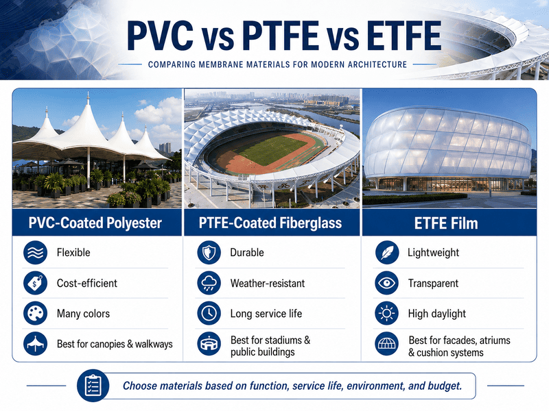
PVC, PTFE, and ETFE Comparison
| Material | Main Characteristics | Typical Cost Position | Common Applications |
|---|---|---|---|
| PVC-coated polyester | Flexible, easy to fabricate, with a broad range of colors and translucency levels. | Initial cost is often easier to control. | Car park canopies, entrance roofs, walkways, and general shade structures. |
| PTFE-coated fiberglass | Good dimensional stability and long-term weather resistance. | The initial cost is usually higher. | Stadiums, transport facilities, public buildings, and permanent large-span roofs. |
| ETFE film | Very lightweight and highly transparent; available as single-layer film or pneumatic cushions. | Must be evaluated as a complete envelope system. | Transparent roofs, atriums, daylighting enclosures, and large public spaces. |
This comparison is suitable for early screening only. Final selection should be based on the actual product data, structural loads, local codes, environmental exposure, maintenance strategy, and total system budget.
PVC-Coated Polyester Membrane
A PVC membrane is generally made from a polyester base fabric with PVC coatings and, in many architectural products, an additional surface treatment. It is flexible, suitable for heat welding and patterning, available in different strengths, colors, and light transmission levels, and compatible with many tensioned forms.
PVC is commonly considered for car park canopies, commercial entrances, covered walkways, school activity areas, and general landscape shade structures. It is often attractive where initial investment, design flexibility, and straightforward fabrication are important.
However, “PVC membrane” is not a complete technical specification. A quotation or drawing should identify the manufacturer and product, warp and weft strength, tear and seam performance, coating and surface finish, fire classification, color, light transmission, and warranty conditions. Products described by the same generic material name may have very different long-term performance and prices.
PTFE-Coated Fiberglass Membrane
A PTFE membrane uses a fiberglass fabric as the load-bearing reinforcement and a PTFE coating as the exposed surface. It is commonly selected for permanent projects that require good dimensional stability, strong resistance to ultraviolet exposure and outdoor weathering, and a surface that can remain relatively easy to clean.
Typical applications include stadium roofs, transport facilities, large public buildings, and permanent long-span canopies. Fabrication, packing, transport, and installation require careful control because fiberglass reinforcement can be sensitive to folding, crushing, and poor handling.
Good membrane durability does not eliminate the need to manage the rest of the system. Long-term performance also depends on seam quality, cable and fitting selection, metal corrosion protection, waterproof interfaces, drainage design, and installation quality.
ETFE Film and Cushion Systems
ETFE is a lightweight, transparent polymer film used as a single mechanically tensioned layer or as two-, three-, or multi-layer pneumatic cushions. Its low weight and high light transmission make it suitable for atriums, transparent roofs, large daylighting spaces, and public-building envelope systems.
Printing, frit patterns, and multi-layer configurations can be used to adjust daylight and solar shading. However, an ETFE project normally includes more than the film itself. A cushion system may also require aluminum perimeter frames, clamping and sealing details, supporting steelwork, low-pressure air units, distribution pipes, pressure controls, electrical equipment, monitoring, installation, and commissioning.
For that reason, ETFE should be priced as a complete envelope system. Cushion geometry, number of layers, frame design, inflation equipment, controls, interfaces, maintenance access, and drainage can all have a significant effect on cost.
Do Not Ignore Cables, Steelwork, and Connection Materials
The membrane is only one part of the structure. The project may also require structural steel, galvanized or painted components, stainless-steel or structural cables, cable terminations, tensioning devices, high-strength bolts, connection plates, aluminum edge profiles, anchor bolts, and reinforced-concrete foundations.
Material grade, corrosion protection, drainage, and connection detailing affect safety, maintenance, and lifecycle cost. In coastal, high-humidity, salt-laden, or industrial environments, particular attention should be paid to cable ends, enclosed connection gaps, dissimilar-metal contact, coating systems, and areas where water may remain trapped.
How to Select PVC, PTFE, or ETFE
No single material is best for every project. A practical early-stage selection can begin with the following priorities:
| Main Project Priority | Material to Evaluate First |
|---|---|
| Control initial investment | PVC-coated polyester |
| Use a wider range of colors or flexible forms | PVC-coated polyester |
| Build a typical car park or commercial canopy | PVC-coated polyester |
| Provide a permanent, long-term roof | PTFE-coated fiberglass |
| Prioritize dimensional stability and weather resistance | PTFE-coated fiberglass |
| Use a membrane that will be difficult to replace later | PTFE-coated fiberglass |
| Maximize natural light or transparency | ETFE film |
| Create a multi-layer transparent cushion envelope | ETFE film |
A sound material selection process is to define the building function and expected service life first; review wind, snow, rainfall, ultraviolet exposure, temperature, and corrosion conditions; confirm fire, light transmission, shading, and maintenance requirements; establish the structural span and support strategy; compare total system cost; and then complete the design using verified product data and review the required certifications, warranty, and supply scope.
The most expensive material is not automatically the best choice. The selected system should match the project function, structural form, environmental exposure, maintenance capability, design life, and budget.
Tensile Membrane Structure Cost: What Determines the Price?
One of the first questions many owners ask is, “How much does a tensile membrane structure cost per square meter?”
A unit rate can help with a very early budget, but it cannot represent the final project price. A tensile structure is a complete engineered system that may include design, membrane fabrication, cables, steelwork, connections, foundations, transport, lifting equipment, installation, drainage, commissioning, and handover documentation.
What Is Included in Tensile Structure Cost?
| Cost Category | Typical Scope |
|---|---|
| Design and engineering | Concept design, form-finding, structural analysis, connection design, and construction drawings. |
| Membrane system | Material, patterning, cutting, welding, reinforcement, and edge fabrication. |
| Cable system | Cables, end fittings, connectors, and tensioning devices. |
| Supporting steelwork | Columns, masts, arches, perimeter beams, plates, and corrosion protection. |
| Foundations | Excavation, reinforcement, concrete, anchor bolts, and embedded items. |
| Transport and installation | Packing, delivery, unloading, cranes, access equipment, membrane installation, and tensioning. |
| Associated works | Gutters, drainage, lighting supports, waterproof interfaces, and control equipment are required. |
| Inspection and handover | Adjustments, inspection records, as-built drawings, material documents, and maintenance information. |
Before comparing suppliers, confirm that the quoted scopes are the same. One offer may cover membrane fabrication only; another may include steelwork but exclude foundations, while a third may omit engineering, cranes, drainage, or site tensioning. Total prices are not directly comparable when the scope boundaries differ.
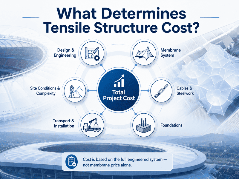
Main Factors That Affect Tensile Structure Cost
1. Structural Span and Support Strategy
Covered area mainly affects membrane quantity, while span has a major influence on cable forces, steel member sizes, connection demand, foundation reactions, and installation difficulty. As span increases, cables may carry higher tension, columns or masts may become larger, connections may become more specialized, and foundations may need to resist greater horizontal and uplift forces.
Two projects with the same area can therefore have very different costs if one uses several shorter repeated modules and the other uses a small number of long spans.
2. Membrane Type and Complete System Configuration
Material cost depends on product type and grade, strength, roll width, fire and daylight requirements, surface treatment, patterning waste, seam layout, edge fabrication, local reinforcement, and installation method.
PVC can often help control initial investment. PTFE is commonly considered for long-term permanent projects. ETFE must be evaluated together with frames, seals, supports, and any required inflation and control systems. On large or complex projects, differences in steelwork, foundations, and site installation can be more significant than the difference in membrane price.
3. Membrane Geometry and Connection Complexity
Complex forms may require more high and low points, cables, supports, custom connections, membrane panels, welds, reinforcement, material allowance, and site adjustment. Regular, repeated, and standardized modules are normally easier to engineer, fabricate, install, and price.
Good tensile architecture is not defined by maximum geometric complexity. It is the result of balancing appearance, structural performance, drainage, buildability, maintenance, and budget.
4. Foundations and Ground Conditions
Although the completed roof is lightweight, membrane prestress and cable forces can create significant horizontal loads, uplift, and overturning moments at the foundations. Foundation cost may be affected by soil bearing capacity, groundwater, underground services, excavation constraints, uplift and sliding requirements, restricted construction space, and connections to existing buildings.
Where reliable ground information is not available, an early foundation allowance is usually based on assumptions. A firm price should be developed after support reactions, ground conditions, and construction scope are better defined.
5. Transport, Access, and Site Installation
Installation cost can change substantially with transport distance, road and gate dimensions, crane access, storage space, membrane laydown area, work-at-height requirements, night work, phased installation, live traffic, occupied buildings, and coordination with other contractors.
A structure installed on an open site may cost considerably less to erect than the same structure in a restricted commercial area.
6. Engineering, Approval, and Handover Scope
Project cost may also include architectural coordination, form-finding, structural analysis, local engineer review, approval documents, shop drawings, site surveys, technical supervision, installation guidance, as-built information, and future inspection or maintenance services.
A lower initial quotation does not always mean a lower final cost. Engineering, foundations, cranes, building interfaces, or drainage omitted from an early offer may later appear as variations.
Why a Price per Square Meter Can Be Misleading
A unit rate is useful only when the membrane grade, area, span, support arrangement, geometric complexity, foundation conditions, site access, and quotation scope are reasonably similar.
For example, a regular short-span canopy with standardized connections and open-site installation is not directly comparable with an irregular long-span roof that has multiple high and low points, custom connections, high uplift reactions, and restricted access. The covered areas may be identical, but the engineering, steelwork, foundations, and installation costs will not be.
Why Supplier Quotations Can Differ Significantly
| Possible Difference | What to Check |
|---|---|
| Engineering scope | Does the price include form-finding, structural analysis, connections, and construction drawings? |
| Material grade | Are the manufacturer, product, strength, finish, fire classification, and certification stated? |
| Membrane fabrication | Does the scope include patterning, cutting, welding, reinforcement, and edge fabrication? |
| Cables and steelwork | Are columns, beams, cables, fittings, plates, bolts, and corrosion protection included? |
| Foundations | Are foundation design, excavation, concrete, reinforcement, and anchors included? |
| Transport and installation | Are delivery, unloading, cranes, access equipment, membrane installation, and tensioning included? |
| Associated works | Are drainage, lighting supports, waterproof interfaces, controls, and testing included? |
| Warranty | Does the warranty apply to the membrane product, fabrication, installation, or the complete system? |
Prices should be compared only after the technical scope and contract boundaries have been aligned.
How to Control Tensile Membrane Structure Cost
The most effective cost control normally takes place during concept design. Practical measures include using regular or repeatable modules, avoiding unnecessary long spans, confirming support and foundation locations early, selecting material according to the actual service-life requirement, limiting unnecessary high and low points, standardizing cables and connections, resolving drainage during concept design, planning transport and lifting routes, and minimizing changes after fabrication has started.
Cost optimization should never be achieved by reducing required prestress, removing essential components, lowering material performance without verification, or omitting structural analysis. Good optimization removes unnecessary complexity while maintaining safety, drainage, durability, and buildability.
Tensile Membrane Project Planning: What to Prepare Before You Start
The quality of the early project information has a direct effect on the reliability of the concept, budget, and schedule. Clear information helps the design team assess whether a tensile membrane structure is suitable, where supports can be placed, which material system may be appropriate, how large the foundations may be, and what installation method is realistic.
If the only information available is a reference image and an approximate area, the proposal will contain many assumptions about span, height, support positions, drainage, foundations, and access. If those assumptions do not match the site, the project may require new form-finding, revised supports, updated connections, or a different material system.
Minimum Information for an Initial Discussion
You do not need complete construction drawings before contacting a design team. The four most useful starting items are:
- Project location.
- Required coverage dimensions.
- Intended use of the structure.
- Site photographs or available drawings.
Tensile Structure Project Information Checklist
| Information Category | What to Provide | Why It Is Needed |
|---|---|---|
| Project location | Country, city, and specific site. | Identifies codes, climate, logistics, and approval requirements. |
| Intended use | Shade, rain protection, daylighting, entrance cover, or complete roof. | Defines performance expectations. |
| Coverage dimensions | Length, width, and actual protected area. | Establishes project scale. |
| Height and clearance | High points, low points, and minimum clear height. | Affects form, drainage, and use of the space. |
| Site information | Photographs, plans, elevations, surveys, or CAD files. | Supports analysis of boundaries, supports, and installation access. |
| Architectural requirements | Color, translucency, transparency, reference form, and building interfaces. | Guides the design direction. |
| Expected service life | Temporary, medium-term, or permanent use. | Influences membrane grade and corrosion protection. |
| Environmental conditions | Wind, snow, rainfall, temperature, ultraviolet exposure, and corrosion risk. | Supports structural and material selection. |
| Ground information | Geotechnical data, underground services, and foundation restrictions. | Helps define foundation locations and types. |
| Construction conditions | Delivery routes, crane access, storage, laydown area, and working restrictions. | Influences erection method and installation cost. |
| Project schedule | Design, approval, production, foundation, and installation dates. | Supports a realistic delivery plan. |
| Budget range | Total expected project investment. | Helps control material, span, and complexity. |
How to Take Useful Site Photographs
Photograph the site from several directions and include the full coverage area, adjacent façades, possible column or anchor positions, roads and vehicle entrances, drainage outlets, visible services or equipment, and any trees, walls, signs, or structures that may affect construction. A known reference dimension in the photograph can help the team understand scale.
Photographs do not replace a formal survey, but they can improve the quality of an early concept and quotation.
When Should the Membrane Material Be Selected?
It is usually unhelpful to lock the project into a specific membrane product before the function, environment, structural form, and performance requirements are understood.
A more reliable sequence is:
- Define the intended use.
- Set the expected service life.
- Review the site, climate, and corrosion conditions.
- Confirm fire, daylight, shading, and maintenance requirements.
- Compare PVC, PTFE, and ETFE at the system level.
- Establish the structural form, span, and support boundaries.
- Use verified product data in form-finding and structural analysis.
- Select the final product after reviewing performance, cost, certification, and supply scope.
The general material direction can be discussed during concept design, but the final product should be coordinated with the structural calculations, project specification, and applicable local requirements.
How to Obtain a More Reliable Tensile Structure Quotation
Provide the project location, length, width, height, minimum clearance, site photographs, available drawings or CAD files, intended use, reference appearance, expected service life, material preferences or performance targets, budget range, target completion date, ground information, and known construction restrictions.
Ask the supplier to state clearly whether the quotation includes engineering; membrane brand and product; cables and steelwork; corrosion protection; foundations; delivery; unloading; cranes; access equipment; installation; tensioning; drainage; building interfaces; handover documents; and warranty.
The more complete the information, the fewer assumptions the quotation will contain and the lower the risk of later design changes or additional costs.
What to Confirm in the Quotation and Contract
| Work Item | Point to Confirm |
|---|---|
| Concept design | Does it include the membrane form and support arrangement? |
| Form-finding | Are the equilibrium geometry and prestress design included? |
| Structural analysis | Does it include the membrane, cables, steelwork, connections, and foundation reactions? |
| Construction drawings | Who prepares them, and are connection details included? |
| Local review and approval | Who is responsible, and are related fees included? |
| Membrane specification | Are the manufacturer, product, strength, finish, color, and fire performance stated? |
| Membrane fabrication | Are patterning, welding, reinforcement, and edge fabrication included? |
| Cables and steelwork | Are fittings, connections, bolts, and corrosion protection included? |
| Foundations | Are design, excavation, reinforcement, concrete, and anchors included? |
| Transport and unloading | Who is responsible, and where does delivery end? |
| Cranes and access equipment | Are lifting and work-at-height equipment included? |
| Installation and tensioning | Does the scope include complete erection, adjustment, and final tensioning? |
| Drainage and building interfaces | Are gutters, outlets, waterproofing, and interface details included? |
| Handover documents | Will material records, inspection reports, and as-built drawings be supplied? |
| Warranty and maintenance | What is covered, for how long, and under what conditions? |
The membrane, cables, steelwork, connections, and foundations must use consistent coordinates, levels, boundaries, and reactions. Late changes to support positions, elevations, or membrane edges can affect form-finding, prestress, cable forces, foundation reactions, cutting patterns, drainage, and installation sequence. Significant changes should be checked and documented by the responsible design team.
FAQ
Does a Tensile Membrane Structure Require Form-Finding?
Mechanically tensioned membrane structures normally require form-finding. Their stable geometry depends on the support boundaries, surface curvature, material behavior, and prestress. An arbitrary architectural surface should not be used directly for fabrication.
Can a Tensile Membrane Structure Be Made in Any Shape?
No. Tensile membranes offer considerable architectural freedom, but the final form must still provide structural stability, effective drainage, suitable clearance, buildable connections, practical patterning, and an achievable installation method.
Can a Tensile Structure Be Priced per Square Meter?
A unit rate can support a very early budget, but a formal quotation must also consider span, support strategy, material grade, steelwork, connections, foundations, drainage, transport, and site installation conditions.
Should the Membrane Be Tensioned as Tight as Possible?
No. Prestress levels and the site tensioning sequence must follow the engineering design. Excessive tension can increase membrane stress, cable forces, connection demand, steel loads, and foundation reactions.
How Can I Tell Whether a Tensile Structure Quotation Is Complete?
Check whether it includes design, membrane specification and fabrication, cables, steelwork, connections, foundations, corrosion protection, transport, unloading, cranes, installation, tensioning, drainage, building interfaces, handover documents, and warranty. Quotations are comparable only when their technical scope and exclusions are aligned.
Conclusion
A successful tensile membrane project depends on four connected areas: a complete design process, a suitable material system, a realistic total-cost assessment, and clear early project information.
The design must produce a stable form, a complete load path, effective drainage, buildable connections, and a practical installation sequence. The material must match the required service life, appearance, light transmission, climate, maintenance strategy, and budget. Cost comparisons must include the whole system rather than the membrane price or area alone.
Before detailed design begins, organize the project location, coverage dimensions, intended use, photographs and drawings, clearance and drainage requirements, expected service life, budget range, and target schedule.
A buildable tensile membrane structure should meet five basic tests: the function suits the project, the form can be constructed, the engineering is verifiable, the materials match the requirements, and the full project scope and cost are clearly defined.

She has over 20 years of experience in tensile membrane structure design, engineering, and manufacturing, with extensive expertise in delivering custom solutions for commercial and architectural projects.