Tensile structure installation involves much more than placing a membrane over a steel frame and pulling it tight. A successful project requires the foundations, anchor points, steel supports, cable system, membrane panels, connection hardware, and drainage details to work together as one coordinated system.
The installation process normally includes site verification, steel erection, membrane inspection, lifting and positioning, initial connection, progressive membrane tensioning, final inspection, and project handover.
A problem at any stage can affect the final membrane geometry, pretension distribution, connection safety, and drainage performance. Incorrect anchor locations may prevent a membrane panel from reaching its fixing points. Incorrect panel orientation may result in removal and reinstallation. An unsuitable tensioning sequence may create wrinkles, uneven loading, localized overstress, or unintended low points where water can collect.
This step-by-step guide explains the complete tensile structure installation process in the order it usually takes place on site. It is intended to help project owners, architects, contractors, and site managers understand:
- What must be checked before installation begins
- How the supporting steelwork and cable system should be prepared
- How membrane panels should be protected, lifted, and positioned
- Why membrane tension must be applied gradually and evenly
- How to identify common installation problems
- How to determine whether the finished structure is ready for acceptance
Technical note: This article provides general installation guidance. Project-specific drawings, engineering calculations, lifting plans, approved method statements, membrane supplier instructions, and local safety regulations must always take priority. Membrane installation and tensioning should be supervised by professionals with relevant tensile structure experience.
What Does Tensile Structure Installation Include?
A tensile structure is not a single component. It is a coordinated structural system that may include the following:
- Concrete foundations, embedded plates, and anchor bolts
- Steel columns, masts, arches, or other rigid supports
- Main cables, edge cables, tie cables, and cable-end fittings
- PVC-coated polyester, PTFE-coated fiberglass, or other architectural membrane materials
- Corner plates, membrane clamps, aluminum profiles, and compression systems
- Turnbuckles, pins, bolts, and other adjustable or fixed connections
- Gutters, outlets, waterproofing details, and drainage interfaces
From an installation perspective, the work can be divided into two closely related parts.
The first is the installation of the supporting system. This includes checking foundations and anchors, erecting steel components, installing cables, and maintaining temporary stability.
The second is the tensile membrane installation. This includes inspecting, unpacking, unfolding, lifting, positioning, initially connecting, and progressively tensioning the membrane panels.
These activities cannot be treated independently. Steel coordinates, elevations, and inclinations define the membrane boundary geometry. Cable lengths and adjustment positions affect whether the membrane can reach its connections. Once tensioned, the membrane transfers loads back into the cables, steel supports, and foundations.
The objective is therefore not simply to create a smooth-looking surface. The complete structure must achieve its intended geometry, pretension, connection condition, and drainage performance.
Tensile Structure Installation Process at a Glance
A typical installation can be divided into seven stages:
| Installation Stage | Main Work | Completion Requirement |
|---|---|---|
| Step 1 | Review documents and verify site conditions | Drawings are approved, and foundations, anchors, and access are ready |
| Step 2 | Install steelwork and the cable system | The structure is stable, aligned, and correctly positioned |
| Step 3 | Inspect, unpack, and unfold the membrane | Panel identification and orientation are correct, with no visible damage |
| Step 4 | Lift and initially position the membrane | The panel reaches the intended connection area safely |
| Step 5 | Complete initial connections and alignment | Main corners and boundaries are connected without significant twisting |
| Step 6 | Tension and adjust the membrane progressively | Geometry, boundary position, and pretension reach project requirements |
| Step 7 | Complete inspection and handover | Structure, membrane, connections, drainage, and records are accepted |
The exact sequence may vary according to structure size, membrane panel count, connection system, lifting method, and site conditions.
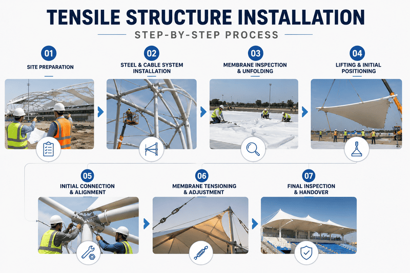
However, the basic logic remains the same:
Verify the foundations and supporting structure before installing the membrane. Establish the basic membrane geometry before applying final pretension.
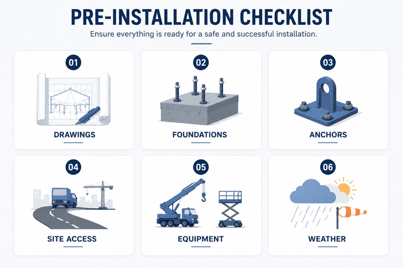
What Should Be Prepared Before Tensile Structure Installation?
Installation quality is often determined before the membrane is lifted.
The main question for the project team is not simply, “When can lifting begin?” The more important question is whether the drawings, dimensions, foundations, equipment, access, weather, and work organization are ready for controlled installation.
Review the approved installation documents.
Before arriving on site, the installation team should obtain and review all relevant documents, including:
- General arrangement and structural drawings
- Foundation, embedded plate, and anchor-bolt layouts
- Steel fabrication and component identification drawings
- Membrane panel identification and unfolding drawings
- Cable and end-connection details
- Membrane lifting points and lifting plans
- Temporary support requirements
- Steel erection sequence
- Membrane connection and tensioning sequence
- Project-specific pretension and acceptance requirements
- Method statements, risk assessments, and emergency procedures
- Inspection, testing, and handover requirements
The site team should not rely on a general arrangement drawing alone. Membrane orientation, plate direction, component numbering, tensioning order, and temporary-support removal may need to be determined from several coordinated drawings.
Before work starts, the project manager, site supervisor, surveyor, lifting supervisor, and tensile membrane installation team should complete a joint technical briefing.
The briefing should confirm that:
- Everyone is using the latest approved drawing revision
- Installation responsibilities are clearly assigned
- Inspection hold points are understood
- Communication procedures are agreed
- Stop-work conditions are defined
- Deviations will be reported and approved before correction
Verify Foundations and Anchor Points
Before steel erection, the foundations, embedded plates, and anchors should be surveyed and inspected.
Key checks include:
- Horizontal coordinates of anchor bolts or embedded plates
- Anchor-bolt spacing, projection, and vertical alignment
- Foundation and base-plate elevations
- Anchor orientation and specified inclination
- Actual distances between support points
- Concrete surface and edge condition
- Whether anchors have been bent, repaired, replaced, or modified
- Whether the foundation can support installation-stage loads
Permitted tolerances and concrete-strength requirements should come from the project drawings, the structural engineer, the inspection results, and applicable regulations.
If anchors do not comply, the installer should not attempt to compensate by enlarging base-plate holes, forcing steel components into position, or applying excessive membrane tension.
A controlled correction process should be followed:
- Record actual measurements and site photographs.
- Compare the results with the approved drawings.
- Report the deviation to the responsible engineer or specialist contractor.
- Obtain an approved corrective solution.
- Complete the corrective work.
- Repeat the survey before installation continues.
Unresolved anchor deviations can lead to steelwork misalignment, difficult membrane connections, abnormal corner loading, membrane displacement, and unintended drainage low points.
Check Site Access and Working Areas
Good site planning reduces unnecessary material handling and protects the membrane from contamination, abrasion, and damage caused by other trades.
Confirm that:
- Cranes, forklifts, and work platforms can enter safely
- Crane outrigger areas have adequate bearing capacity
- A dedicated unloading and membrane unfolding area is available
- Steel components can be stored in installation sequence
- The unfolding area is clean, level, and free from standing water
- The ground is free from exposed reinforcement, sharp stones, weld spatter, and oil
- Crane operating zones do not conflict with buildings or other trades
- Personnel exclusion and lifting-control zones are established
- Temporary power, lighting, drainage, and communication are ready
The membrane unfolding area should be separated from welding, cutting, painting, vehicle routes, and heavy pedestrian traffic.
Where complete separation is not possible, suitable barriers, covers, and protective procedures should be provided.
Confirm Suitable Weather Conditions
Large membrane panels are relatively lightweight but can present a substantial surface area to the wind once unfolded or suspended.
If a panel rotates, flaps, inflates, or moves unexpectedly, it may be difficult to control safely.
Before installation, review current conditions and the short-term forecast, considering:
- Limits stated in the approved lifting plan
- Crane and equipment manufacturer requirements
- Membrane panel size, weight, and lifting configuration
- Local wind effects caused by terrain and nearby buildings
- Rain effects on ground bearing and work at height
- Lightning, temperature, and visibility
A single maximum wind speed should not be applied to every tensile structure project. Acceptable conditions depend on membrane characteristics, lifting configuration, equipment limitations, site exposure, and the project risk assessment.
Weather should also be monitored throughout installation. Conditions may change while a panel is suspended, connected, or partially tensioned.
Prepare Equipment and Membrane Protection Materials
Required equipment depends on the structure span, installation height, panel size, connection system, and site conditions.
| Purpose | Typical Equipment or Materials |
|---|---|
| Unloading and handling | Cranes, forklifts, transport trolleys, soft lifting slings |
| Work at height | Mobile elevated work platforms, scaffolding, fall-protection systems |
| Temporary pulling | Chain blocks, winches, tag lines, and lifting devices |
| Connection adjustment | Turnbuckles, hand tools, torque tools, and temporary clamps |
| Membrane tensioning | Project-specified tensioning tools, hydraulic equipment, or measuring devices |
| Surveying | Total stations, levels, measuring tapes, and elevation equipment |
| Membrane protection | Clean sheets, soft padding, and edge protectors |
| Site safety | Helmets, harnesses, barriers, and communication equipment |
All equipment should be inspected before use. Its rated capacity, working range, and intended use must be suitable for the task.
Pre-Installation Checklist
Before steel erection or membrane lifting begins, confirm that:
- The latest approved drawings are available
- Foundations, anchors, and support points have been surveyed
- Identified deviations have been resolved
- Steel, cable, and membrane panel identification is clear
- The lifting and tensioning sequence has been briefed
- Cranes and access equipment have been inspected
- The membrane unfolding area is clean and protected
- Weather conditions are suitable
- Exclusion zones and communication procedures are established
- Emergency and stop-work procedures are understood
- Inspection responsibilities are assigned
Only after these conditions are satisfied should physical installation begin.
Step 1: Review Drawings and Verify Foundations, Anchors, and Site Conditions
The first physical step is to confirm that actual site conditions match the approved documents.
The survey should not examine each anchor in isolation. It should also verify the relationship between all supporting points.
A single anchor may have only a small deviation. However, if several anchors move in different directions, the overall structural boundary can change significantly. This may prevent the steelwork from fitting correctly, make membrane connections difficult, or produce uneven tension later.
A practical verification sequence is the following:
- Establish a common coordinate and elevation reference.
- Survey all main support points, embedded items, and anchors.
- Check foundation tops, base-plate surfaces, and bearing conditions.
- Compare dimensions across the steel, cable, and membrane drawings.
- Identify site obstacles that may affect lifting or access.
- Prepare survey records and photographs.
- Obtain approval before lifting begins.
Can Anchor Bolts Be Forced Into Alignment?
No. Forcing steel components into position is not recommended.
Mechanical pulling may introduce unintended stress into the column base, anchor bolts, or connection plate. Enlarging holes, bending anchors, or modifying connection components without approval may also compromise performance and acceptance.
Possible causes include the following:
- Incorrect anchor coordinates or spacing
- Steel fabrication errors
- Incorrect base-plate orientation
- Incorrect component identification
- Inconsistent survey references
- Foundation, anchor, or steel deformation
The cause should be identified first. The responsible engineer or specialist contractor should then approve a corrective method.
Installation should continue only after correction and resurveying.
Step 2: Install the Steel Structure, Masts, and Cable System
Once the foundations and anchors are accepted, the supporting structure can be assembled in accordance with the approved erection sequence.
The objective is not only to place the steel components. The structure must also achieve the correct geometry and remain stable during membrane lifting and tensioning.
Complete Ground-Level Preassembly Where Practical
Where site space and lifting capacity allow, some components may be preassembled at ground level, including the following:
- Masts and top fittings
- Beams and connection plates
- Cable ends and adjustment devices
- Supports for membrane clamping systems
- Pins and accessories that can be safely preinstalled
Ground-level preassembly helps verify component numbers, orientation, and connection relationships. It can also reduce work at height.
However, the weight, center of gravity, lifting-point arrangement, and temporary stability of each preassembled unit must be included in the lifting plan.
Erect Supporting Components in the Approved Sequence
When lifting columns, masts, arches, or support frames, verify:
- Lifting points comply with the approved plan
- Component orientation remains controlled
- Column bases or supports are seated correctly
- Temporary bolts and connections are installed
- Reliable temporary bracing is provided
- Alignment, elevation, and verticality comply with the drawings
- The structure remains stable before permanent connections are complete
A steel frame that can stand by itself is not necessarily ready to carry membrane lifting or tensioning loads.
Membrane tensioning may introduce horizontal forces from several directions. Temporary bracing and structural stability must therefore be coordinated with the full installation sequence.
Install Main Cables, Edge Cables, and Connections
During cable installation, check:
- Cable identification, length, and location
- Cable-end and connection-plate orientation
- Pins, retaining devices, and locking components
- Adjustment available in turnbuckles or similar devices
- Potential rubbing or sharp contact with steelwork
- Access for later membrane connection
- Whether temporary slack is required
All cables should not automatically be adjusted to their final condition before membrane positioning.
Cable length, boundary position, and cable force may need to be coordinated during membrane connection and progressive tensioning.
Recheck the supporting structure geometry.
Before membrane lifting, confirm that:
- Columns, masts, and primary supports are correctly positioned
- Designed high and low points are at the required elevations
- Connection plates and cable ends face the correct direction
- Cable routes match the approved drawings
- Membrane contact areas are free from burrs and weld spatter
- Main connection points can be accessed safely
- Temporary bracing will not obstruct membrane installation
- The structure remains stable in its current condition
The membrane should never be used to pull misaligned steelwork back into position. Structural geometry should be corrected before membrane installation begins.
Step 3: Inspect, Unpack, and Unfold the Membrane
The membrane is one of the components most vulnerable to site damage.
Rough ground, sharp edges, sand on footwear, welding sparks, incorrect folding, and unsuitable lifting equipment can cause coating damage, scratches, or permanent creases.
Membrane unpacking and unfolding should take place in a controlled area under the supervision of personnel familiar with panel identification, orientation, and material-handling requirements.
Verify Panel Information Before Unpacking
Before opening the packaging, check:
- Whether the packaging is damaged or wet
- Whether the panel number matches the installation plan
- Whether the membrane type, color, and surface orientation are correct
- Whether unfolding arrows and lifting marks are clear
- Whether matching cables, clamps, and connections are available
- Whether there are signs of transport damage
For multi-panel structures, unloading and unpacking should follow the intended installation sequence.
Prepare a Clean and Protected Unfolding Area
The membrane should be unfolded on a clean, continuous, level protective surface.
Workers should check footwear and tools before entering the area. Bolts, clamps, or metal components should not be placed directly on the membrane.
The area should be separated from:
- Welding and cutting
- Oils, paints, and chemicals
- Vehicle and pedestrian traffic
- Exposed reinforcement and rough concrete
- Sharp steel corners
- Work that produces sparks or hot particles
Stiffer materials, including some PTFE-coated fiberglass membranes, require particular care to avoid hard folds and pressure on folded areas.
Material-specific handling instructions should always be followed.
Inspect Membrane Condition and Orientation
Once unfolded, check:
- Overall panel shape
- High-point, low-point, and corner identification
- Warp, weft, or fabrication markings
- Welded-seam position and direction
- Edge and corner reinforcement
- Cable pockets, clamp positions, and openings
- Scratches, contamination, creases, or coating abnormalities
All irregularities should be documented before lifting.
Panel orientation must be verified while the membrane is still on the ground. Discovering an orientation error after lifting increases both installation time and damage risk.
Step 4: Lift and Initially Position the Membrane
The purpose of lifting is not to pull the membrane directly into its final tensioned position.
The objective is to move it safely into the designed connection area and establish a controlled, adjustable starting position.
Use Approved Lifting Points and Soft Slings
Lifting-point locations should follow the installation drawings, lifting plan, or membrane supplier’s instructions.
Slings should not be attached to ordinary membrane areas, seams, or unreinforced zones unless specifically approved.
Before lifting, confirm that:
- Slings and rigging are in good condition
- Lifting points match the approved plan
- The folded panel supports controlled unfolding
- The lifting path avoids steelwork and obstructions
- Tag lines are available where required
- Communication methods are clear
- A stop procedure is defined for changing weather or equipment problems
Control Membrane Movement During Lifting
Lifting should be slow and controlled. Sudden acceleration, abrupt stopping, and rapid directional changes should be avoided.
Large panels may require several tag lines to limit rotation. Personnel handling the lines should remain outside potential snap-back zones.
Unauthorized personnel should remain outside the lifting area. No one should stand beneath a suspended membrane or within a potential fall zone.
Protect Membrane-to-Steel Contact Areas
Soft padding and edge protection should be placed where the membrane may contact:
- Steel-plate edges
- Exposed threads and bolt ends
- Pins and clamp corners
- Temporary-bracing connections
- Raised welds or metal burrs
- Potential pinch points
Once tension develops, even a small sharp contact point can cause coating wear or localized stress concentration.
Bring Main Connection Points Into Position
Move the main corners, high points, or low points toward their designated connection areas in the approved sequence.
Confirm that:
- The panel is not twisted or inverted
- The correct surface faces outward
- Each connection retains adjustment
- Panel weight is not concentrated at one corner
- The membrane is not dragged across steelwork
- Main connection areas remain reasonably balanced
Recheck the panel number, orientation, and connection relationship before initial fixing begins.
Step 5: Complete Initial Connections and Align the Membrane
Initial connection is the transition from a suspended panel to a membrane that can be tensioned in a controlled way.
The objective is not to tighten the membrane immediately. The main connections should first be completed in the approved order while preserving correct orientation, position, and load distribution.
Follow the Approved Membrane Installation Sequence
Different tensile structures may begin with high points, low points, main corners, or opposing boundaries.
There is no single sequence suitable for every structure.
The correct membrane installation sequence depends on the following:
- Panel shape and boundary configuration
- Direction of designed pretension
- Current steelwork stability
- Main- and edge-cable adjustment methods
- Lifting-equipment exit path
- Current distribution of membrane weight
- Available connection adjustment
The site team should not connect whichever point is easiest to reach.
An incorrect sequence can cause panel displacement, concentrated loading, and difficulty during later tensioning.
Preserve Adjustment During Initial Fixing
After the main corners are positioned, install progressively:
- Corner plates
- Edge clamps
- Aluminum profiles
- Compression assemblies
- Membrane edge cables
- Temporary pulling devices
- Remaining boundary connections
Do not bring one corner or boundary to final tension while other areas remain unconnected.
Prematurely tightening one side may shift the entire membrane and make the opposite side difficult to connect.
Check Alignment and Twisting
Inspect the panel from several directions and check:
- Whether the membrane center has shifted
- Whether seams follow the intended direction
- Whether corner reinforcement is seated correctly
- Whether any edge has turned over
- Whether the membrane is twisted around a cable or connection
- Whether wrinkle direction is consistent with the expected tensioning pattern
- Whether one corner carries excessive weight
Some looseness and wrinkling are normal before full pretension is established.
However, significant displacement, twisting, or abnormal wrinkle direction should be corrected before formal tensioning begins.
Step 6: Tension the Membrane Gradually and Evenly
Membrane tensioning is one of the most important stages of tensile structure installation.
Its purpose is not simply to remove visible wrinkles. The membrane must form the designed three-dimensional surface, develop stable biaxial tension, and transfer loads correctly into the cables, supporting steelwork, and foundations.
Why Does the Untensioned Membrane Look Too Small?
A membrane panel is not always cut to the exact dimensions of the final installed surface.
During design and fabrication, the cutting pattern may be reduced according to the membrane’s biaxial behavior, required pretension, and final geometry.
Controlled stretching during installation allows the membrane to reach its intended shape and pretension.
A panel that does not easily reach its connection is therefore not automatically defective.
Before increasing pulling force, verify:
- Anchor and support locations
- Steelwork elevations and geometry
- Membrane panel identification and orientation
- Cable and connection positions
- Available adjustment in tensioning devices
The membrane should never be forced into position before the cause of the mismatch has been identified.
Apply Pretension in the Approved Sequence
The target pretension, adjustment range, sequence, and verification method must come from the project drawings and approved tensioning plan.
A typical progressive sequence may include:
- Remove major slack.
- Establish the basic three-dimensional form.
- Balance opposing corners and boundaries.
- Increase tension in controlled stages.
- Check membrane position and geometry after each stage.
- Coordinate main cables, edge cables, and the membrane surface.
- Reach the project-specific final condition.
- Lock and inspect all adjustable connections.
Adjustment increments should remain controlled. After each round, inspect the entire membrane and supporting structure.
Pretension values or adjustment movements from another project should not be copied directly.
Maintain Balance Between Opposing Boundaries
A tensile membrane behaves as an interactive system. Adjusting one corner or edge cable may affect the geometry and loading of a much larger area.
Monitor:
- Whether opposing corners progress together
- Whether edge-cable curves remain smooth
- Whether the membrane moves continuously toward one side
- Whether high and low points change unexpectedly
- Whether adjustment devices reach their limits too early
- Whether temporary supports receive unintended loads
- Whether masts or steel connections move abnormally
Do not continue tightening one connection merely to remove a local wrinkle.
Wrinkles may result from incorrect positioning, steelwork geometry, unequal cable lengths, or an unbalanced sequence—not only insufficient tension.
Common Membrane Tensioning Problems
| Site Condition | Possible Cause | Check First |
|---|---|---|
| Persistent diagonal wrinkles | Unbalanced opposing tension | Opposite corners, edge cables, and sequence |
| Localized sagging | Low tension or incorrect boundary position | Support elevations, edge cables, and connection adjustments |
| Concentrated corner deformation | Incorrect corner position or load distribution | Corner reinforcement and adjacent boundaries |
| The membrane cannot reach a connection | Anchor, steel, or panel-identification problem | Survey records, component numbers, and orientation |
| Uneven edge-cable curve | Incorrect cable length or adjustment | Cable ends, turnbuckles, and edge connections |
| Unintended low point | Incorrect geometry or tension distribution | High and low points, curvature, and drainage |
| Adjustment reaches its limit early | Incorrect initial position or sequence | Initial adjustment and overall boundary position |
These observations help identify where to investigate, but they do not replace engineering judgment.
If additional tension may damage the membrane, connections, cables, or steelwork, stop the operation and obtain a professional review.
Step 7: Complete Final Inspection and Project Handover
A tensioned membrane is not automatically ready for handover.
Final inspection should cover the membrane, steelwork, cables, connections, pretension condition, drainage, and installation records.
Inspect the Membrane Surface
Check each panel for:
- Cuts, punctures, or significant abrasions
- Coating wear, peeling, or contamination
- Abnormal hard creases
- Damaged seams
- Incorrectly positioned reinforcement
- Persistent wrinkles or local sagging
- Excessive stretching
- Oil, weld spatter, or chemical contamination
- Contact with sharp steel, exposed threads, or rough edges
Where damage is found, record the location, size, and condition with photographs.
Repairs should follow an approved method. Unapproved adhesives, solvents, or patching materials may affect material compatibility, coating performance, and warranty conditions.
Inspect Connections and Cables
Check:
- Bolts, nuts, and washers
- Pins and retaining devices
- Membrane clamps and compression profiles
- Turnbuckles and locking systems
- Main cables, edge cables, and cable ends
- Corner plates
- Column bases and anchor bolts
- Corrosion protection damaged during installation
- Drainage, waterproofing, and sealing details
Adjusted connections should be locked, marked, or recorded according to project requirements.
Verify Geometry and Drainage
Confirm that:
- Designed high and low points are correctly positioned
- The membrane has the required three-dimensional curvature
- Panels are not displaced, inverted, or twisted
- Main- and edge-cable curves are smooth
- No unintended ponding points are present
- Rainwater can reach the designed gutters and outlets
- Required clearances are maintained
- Doors, lighting, and services will not conflict with membrane movement
Drainage inspection should assess the membrane surface, not only gutters and outlets.
Where permitted, a controlled water test may be used to verify drainage performance.
Prepare Handover Records
The handover package may include:
- Pre-installation survey records
- Foundation and anchor inspections
- Steel geometry verification
- Membrane delivery and surface inspections
- Tensioning and adjustment records
- Cable and connection inspections
- Damage and repair approvals
- As-built drawings
- Product technical data
- Cleaning and maintenance instructions
- Warranty documents
- Recommended follow-up inspections
- Photographs of key installation stages
These documents support not only project acceptance but also future inspection, cleaning, repair, and membrane replacement.
Safety Risks During Tensile Structure Installation
Tensile structure installation may combine steel erection, work at height, suspended loads, temporary supports, and loaded tensioning equipment.
Every project should therefore have a dedicated method statement, risk assessment, and emergency procedure coordinated by competent personnel.
Lifting and Suspended Loads
Before lifting, confirm:
- Equipment, rigging, and lifting points are suitable
- Supervisors and signal methods are identified
- Communication is clear
- Lifting routes are unobstructed
- Exclusion and drop zones are established
- Membrane wind-control methods are defined
- Emergency and stop-lifting procedures are understood
- Cranes and work platforms can operate together safely
Personnel should not stand beneath suspended loads or within potential fall zones.
Working at Height
Provide:
- Suitable work platforms or scaffolding
- Compliant fall-protection systems
- Safe access routes
- Tool-drop prevention
- Platform stability and capacity control
- Weather-related stop conditions
- Communication between ground and elevated teams
Workers should not stand on unstable members, unsecured clamps, or cables under adjustment.
Temporary Structural Stability
Some supporting frames only achieve full stability after permanent cables or membranes are installed.
Temporary supports and erection sequences should therefore be planned.
Confirm that:
- The current structure can resist installation loads
- Temporary supports remain compatible with later work
- Cable or membrane adjustment will not cause instability
- Permanent stability is established before temporary support removal
- Sequence changes have been reassessed
A frame should not be assumed safe simply because it can stand without visible movement.
Tensioning, Snap-Back, and Pinch-Point Risks
Control the risk of:
- Personnel standing in the snap-back path of loaded lines
- Hands entering clamps or cable-end pinch points
- Uninspected temporary connections carrying high loads
- Several teams adjusting without coordinated instructions
- Equipment exceeding its capacity or adjustment range
- Sudden membrane movement
- Unauthorized personnel entering loaded areas
A designated person should control all start, stop, and continue instructions.
Stop-Work Conditions
Stop installation when:
- Wind, rain, lightning, or visibility deteriorates
- Cranes, access platforms, or tensioning tools behave abnormally
- Temporary supports or structural connections move
- Membranes, cables, or lifting points are damaged
- Clear communication cannot be maintained
- Tensioning resistance exceeds expectations
- Actual conditions no longer match the approved method
Safety decisions should follow the approved installation plan, equipment requirements, professional judgment, and applicable regulations.
Common Tensile Structure Installation Mistakes
1. Starting Without Resurveying the Anchors
Risk: Misaligned steelwork, difficult membrane connections, and incorrect geometry.
Correct approach: Survey all anchors and resolve deviations before erection.
2. Dragging the Membrane Over Rough Ground
Risk: Coating abrasion, exposed base fabric, or hidden damage.
Correct approach: Use clean protective sheets, soft slings, and edge protection.
3. Connecting Corners Before Confirming Orientation
Risk: Seams, corners, and boundaries do not align.
Correct approach: Verify panel identification and orientation before lifting.
4. Fully Tensioning One Side Too Early
Risk: Panel displacement, difficult opposite-side connections, and uneven loading.
Correct approach: Tension opposing boundaries progressively.
5. Using Excessive Tension to Remove Wrinkles
Risk: Local overload in the membrane, clamps, or steelwork.
Correct approach: Check positioning, geometry, cable length, and sequence first.
6. Removing Temporary Bracing Too Early
Risk: Instability, movement, or permanent deformation.
Correct approach: Remove temporary supports only after permanent stability is confirmed.
7. Ignoring Weather Changes
Risk: A suspended membrane may rotate, inflate, or become uncontrollable.
Correct approach: Monitor weather continuously and use clear stop-work limits.
8. Inspecting Appearance but Not Drainage
Risk: Unintended ponding, additional loading, and long-term deformation.
Correct approach: Check membrane curvature, high and low points, gutters, outlets, and the full drainage path.
How Long Does Tensile Structure Installation Take?
There is no standard duration for every project.
A small standardized canopy may have a relatively simple installation program. A large venue roof, multi-panel free-form structure, or retrofit project within an operating facility may require complex lifting and staged work.
Factors affecting tensile structure installation time include:
- Structural span and installation height
- Steel and cable complexity
- Number, size, and weight of membrane panels
- Connection and tensioning systems
- Foundation and anchor readiness
- Crane and platform access
- Ground-level preassembly
- Number of tensioning and surveying stages
- Coordination with other trades
- Weather and seasonal conditions
- Inspection and approval procedures
- Requirements to maintain public access or operations
To obtain a reliable schedule, provide the specialist contractor with:
- Project location
- General arrangement drawings
- Main dimensions and height
- Support configuration
- Membrane type and panel count
- Site access information
- Foundation and steelwork status
- Planned installation date
- Working-hour restrictions
- Available lifting equipment
Installation time should be estimated from the drawings, quantities, method, equipment, and site conditions—not from membrane area alone.
How to Check Whether the Installation Is Correct
Project owners and managers should confirm that:
- Structural geometry matches the approved drawings
- Columns, masts, beams, and cables are correctly positioned
- Membrane panel identification and orientation are correct
- Main corners and boundary connections are complete
- Clamps, pins, bolts, and locking devices are installed
- The membrane has no significant damage
- No unexplained sagging or concentrated deformation is present
- Reinforcement is correctly seated
- Cable curves are continuous and stable
- Pretension has been verified
- Drainage paths are clear
- No unintended ponding points are visible
- Inspection and maintenance records are complete
Minor surface texture or localized wrinkles should not be used as the only acceptance criterion.
Final acceptance should consider geometry, material behavior, connection condition, pretension, drainage, and professional inspection results.
Conclusion
Successful tensile structure installation begins with accurate surveying and thorough preparation—not when the membrane is lifted.
The foundations, anchors, supporting structure, cable system, access, weather, and lifting equipment must be verified before membrane installation begins. During unpacking, unfolding, and lifting, the membrane must be protected from abrasion, contamination, sharp edges, and incorrect orientation.
After the initial connections are completed, pretension should be developed gradually and evenly according to the approved sequence. Local wrinkles should not be corrected by excessively tightening a single connection without first identifying the cause.
After installation, the team should inspect the membrane surface, structural geometry, cables, connections, pretension, and drainage. Survey, adjustment, repair, and handover records should also be retained.
The project is complete only when the entire system achieves the intended geometry, load-transfer condition, connection security, and drainage performance.
Planning a tensile membrane structure project? Send Yexing your project location, structural dimensions, drawings, membrane requirements, and site conditions. Our team can help evaluate the structure, installation requirements, lifting conditions, and project implementation plan for the next stages of design, fabrication, and on-site installation.
FAQ
What Are the Main Steps in the Tensile Structure Installation Process?
The main steps are site verification, foundation and anchor surveying, steel and cable erection, membrane inspection, lifting and positioning, initial connection, progressive tensioning, final inspection, and project handover.
Each stage affects the next. Foundations define the steel geometry, steel and cables define the membrane boundaries, and the tensioned membrane transfers loads back into the supporting structure.
What Should Be Checked Before Tensile Membrane Installation?
Check the approved drawings, foundations, anchors, steel geometry, cable positions, panel identification, site access, lifting areas, weather, equipment, communication procedures, and stop-work conditions.
Lifting should begin only when the site, structure, equipment, and personnel are ready.
How Long Does It Take to Install a Tensile Structure?
Installation time depends on the span, height, panel count, steel complexity, connection system, equipment access, tensioning stages, inspections, and weather.
A reliable schedule should be based on drawings, quantities, site conditions, and the installation method—not membrane area alone.
Why Does a Membrane Panel Look Too Small Before Installation?
The cutting pattern may be smaller than the final installed geometry so the membrane can develop the required pretension when stretched into position.
However, a panel that cannot reach its connection should not simply be pulled harder. Anchors, steel geometry, panel identification, orientation, cables, and adjustment ranges should be checked first.
Can a Tensile Membrane Be Installed in Windy or Rainy Weather?
It depends on panel size, lifting configuration, site exposure, equipment limits, and the approved safety plan.
There is no single wind-speed limit suitable for every project. The responsible team should establish acceptable conditions using the risk assessment, lifting plan, equipment requirements, and local regulations.
Why Are There Wrinkles After Tensile Membrane Installation?
Wrinkles may result from low tension, incorrect membrane position, wrong orientation, steel geometry errors, unequal cable lengths, or an unbalanced tensioning sequence.
Persistent wrinkles should be investigated before additional tension is applied.
Does a Tensile Structure Need to Be Retensioned After Installation?
It depends on the membrane material, connection system, engineering requirements, supplier instructions, and follow-up inspection results.
Owners should not adjust connections without checking the steelwork, cables, anchors, membrane position, and drainage condition.
How Can You Tell Whether the Installation Is Acceptable?
An acceptable installation should match the approved geometry, have correctly oriented panels, complete connections, stable cable curves, verified pretension, no significant membrane damage, and a clear drainage path.
Final acceptance should also include inspection records, adjustment records, as-built information, and maintenance documentation.

She has over 20 years of experience in tensile membrane structure design, engineering, and manufacturing, with extensive expertise in delivering custom solutions for commercial and architectural projects.